Black & Decker GH710 Type 1 Manual - GH710 - Page 5
Assembly And Adjustment, Components - trimmer
 |
View all Black & Decker GH710 manuals
Add to My Manuals
Save this manual to your list of manuals |
Page 5 highlights
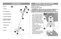
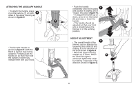
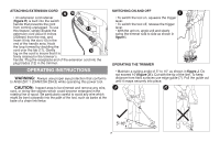
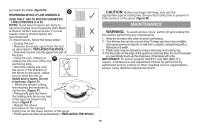
COMPONENTS Figure A A 1. Switch 4 2. Cord Retainer 3. Cord Receptacle 4. Auxillary Handle 5 5. Collar (to adjust height and edge) 6. Motor Housing 7. Edge Guide 8. Guard 9. Spool 7 9 6 8 1 2 3 ASSEMBLY AND ADJUSTMENT ASSEMBLY TOOLS REQUIRED (NOT SUPPLIED): - Phillips Screwdriver INSTALLING THE GUARD WARNING: UNPLUG THE TOOL BEFORE ATTEMPTING TO ATTACH THE GUARD, EDGE GUIDE OR HANDLE. NEVER OPERATE TOOL WITHOUT GUARD FIRMLY IN PLACE. THE GUARD MUST ALWAYS BE ON THE TOOL TO PROTECT THE USER. • Turn the trimmer upside B 2 down so that you are looking down at the spool cap (1). • Turn the guard (2) upside down and slide it onto the 3 motor housing (3). Make 4 sure the tabs (4) on the guard engage the ribs (5) on the motor housing as shown. 5 • Continue to slide the guard on until you hear it "snap" into place. • Using a phillips screwdriver, remove the screw from the guard. 1 • Insert the guard screw as shown in figure C to C complete the guard assembly. • Once the guard is installed, remove the covering from the line cut-off blade, located on the edge of the guard. 5
-
 1
1 -
 2
2 -
 3
3 -
 4
4 -
 5
5 -
 6
6 -
 7
7 -
 8
8 -
 9
9 -
 10
10 -
 11
11 -
12
-
13
-
14
-
15
-
16
-
17
-
18
-
19
-
20
-
21
-
22
-
23
-
24
-
25
-
26
-
27
-
28
-
29
-
30
-
31
-
32
-
33
-
34
-
35
-
36
-
37
-
38
-
39
-
40
 |
 |
