Campbell Scientific Vibrating CRVW3 3-Channel Vibrating-Wire Datalogger
Campbell Scientific Vibrating Manual
 |
View all Campbell Scientific Vibrating manuals
Add to My Manuals
Save this manual to your list of manuals |
Campbell Scientific Vibrating manual content summary:
- Campbell Scientific Vibrating | CRVW3 3-Channel Vibrating-Wire Datalogger - Page 1
INSTRUCTION MANUAL CRVW3 3-Channel Vibrating-Wire Datalogger Preliminary: 1/30/15 Copyright © 2015 Campbell Scientific, Inc. - Campbell Scientific Vibrating | CRVW3 3-Channel Vibrating-Wire Datalogger - Page 2
- Campbell Scientific Vibrating | CRVW3 3-Channel Vibrating-Wire Datalogger - Page 3
CSI to be free from defects in materials and workmanship under normal use and service for twelve months from the date of shipment unless otherwise specified in the corresponding product manual. (Product manuals are available for review online at www.campbellsci.com.) Products not manufactured by CSI - Campbell Scientific Vibrating | CRVW3 3-Channel Vibrating-Wire Datalogger - Page 4
problem, an RMA number will be issued. Please write this number clearly on the outside of the shipping container. Campbell Scientific's shipping address is: CAMPBELL SCIENTIFIC customer at the customer's expense. Campbell Scientific reserves the right to refuse service on products that were exposed - Campbell Scientific Vibrating | CRVW3 3-Channel Vibrating-Wire Datalogger - Page 5
exceed design limits. Be familiar and comply with all instructions provided in product manuals. Manuals are available at www.campbellsci.com or by telephoning IS MADE TO EMBODY THE HIGHEST DEGREE OF SAFETY IN ALL CAMPBELL SCIENTIFIC PRODUCTS, THE CUSTOMER ASSUMES ALL RISK FROM ANY INJURY RESULTING - Campbell Scientific Vibrating | CRVW3 3-Channel Vibrating-Wire Datalogger - Page 6
- Campbell Scientific Vibrating | CRVW3 3-Channel Vibrating-Wire Datalogger - Page 7
4 5. Overview 5 5.1 Measurement Theory 5 5.2 About This Manual 7 6. Specifications 8 7. Installation 9 7.1 Individual Devices and Radio 8.1.1.2 Install the CRVW3 USB Driver 12 8.1.1.3 Network Planner 12 8.1.2 Wiring Temporary Sensors to the CRVW3 13 8.1.3 Providing Temporary Power to the - Campbell Scientific Vibrating | CRVW3 3-Channel Vibrating-Wire Datalogger - Page 8
LED Operation 36 8.2.8.2 Validation with DevConfig 38 8.2.9 Validating CRVW3 Radio Operation 40 8.2.10 Sealing the CRVW3 Enclosure 40 8.3 On-site Manual Data Collection 41 9. Radio Networks 41 9.1 Simple Radio Network Definition 42 9.2 Simple Network Installation Overview 43 9.3 CRVW3-RF451 - Campbell Scientific Vibrating | CRVW3 3-Channel Vibrating-Wire Datalogger - Page 9
Maintenance Visits 83 13. Troubleshooting CRVW3 Networks 84 13.1 Troubleshooting Problems Remotely Using LoggerNet 85 13.2 Troubleshooting Problems by Visiting the CRVW3 Site 85 Appendices A. Updating CRVW3 Firmware A-1 B. Terminal Mode from Connect Screen or DevConfig B-1 C. Aggregating - Campbell Scientific Vibrating | CRVW3 3-Channel Vibrating-Wire Datalogger - Page 10
Power Source Connection to the CRVW3 Charge Terminals 15 CRVW3 USB Connection Location 16 Typical Vibrating-Wire Sensor Lead Colors and Connections ......... 28 CRVW3 Cable Connection and Entry Points 28 Wiring Panel of the CRVW3 29 -ALK Battery Pack Connector Cable and CRVW3 Battery Connection - Campbell Scientific Vibrating | CRVW3 3-Channel Vibrating-Wire Datalogger - Page 11
(Campbell recorder) that measures and stores readings from up to three vibrating-wire sensors. A temperature measurement (usually obtained from a thermistor built-in to the sensor) is also available for each of these three channels. Standard, single-coil-circuit vibrating-wire sensors are supported - Campbell Scientific Vibrating | CRVW3 3-Channel Vibrating-Wire Datalogger - Page 12
CRVW3 3-Channel Vibrating-Wire Datalogger Configuration of devices and Campbell Scientific website: www.campbellsci.com/crvw3 Before using the CRVW3, please refer to the following: • Quick Deploy Guide o a folded card stored within the CRVW3 that contains summarized deployment and use instructions - Campbell Scientific Vibrating | CRVW3 3-Channel Vibrating-Wire Datalogger - Page 13
Vibrating-Wire station in the network. Please consult with your local Campbell Scientific support representative regarding the use of radio options. Also refer Male (pn 27555) • Flat-bladed Screwdriver (pn 1113) • Quick Deploy Guide (folded card, pn 31174) • Desiccant Bag (pn 4905) • Humidity - Campbell Scientific Vibrating | CRVW3 3-Channel Vibrating-Wire Datalogger - Page 14
CRVW3 3-Channel Vibrating-Wire Datalogger Examine the outside label on the device to Guide included with each CRVW3 as a folded card inside the enclosure (pn 31174). You can also view and download the Quick Deploy Guide from the Campbell Scientific website: s.campbellsci.com/documents/us/manuals - Campbell Scientific Vibrating | CRVW3 3-Channel Vibrating-Wire Datalogger - Page 15
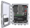
of the CRVW3 are shown in FIGURE 5-1. FIGURE 5-1. Basic Parts of the CRVW3 5.1 Measurement Theory The CRVW3 uses Campbell Scientific VSPECT™ technology (U.S. Patent No. 7,779,690 ) to measure standard, single-coil-circuit vibrating-wire sensors. FIGURE 5-2. CRVW3 Cable Connection and Entry Points 5 - Campbell Scientific Vibrating | CRVW3 3-Channel Vibrating-Wire Datalogger - Page 16
this stage. 3) The measurement system processes the time-series waveform captured from the coil to assess the frequency of the wire's vibration. The basic output of a vibrating-wire sensor is frequency in Hz. Conversion from frequency to engineering units is possible based on a knowledge of how the - Campbell Scientific Vibrating | CRVW3 3-Channel Vibrating-Wire Datalogger - Page 17
sensor as temperature changes occur. To compensate for this effect, many vibrating-wire sensors contain a built-in thermistor or other resistive temperature device. The units of measure). 5.2 About This Manual Please study the remaining sections of this manual to obtain maximum benefit from your - Campbell Scientific Vibrating | CRVW3 3-Channel Vibrating-Wire Datalogger - Page 18
Section 13, Troubleshooting CRVW3 Networks, provide guidance for the operation, maintenance, and troubleshooting required when and 3 thermistor/RTD (temperature) measurements 1 s per sensor (VW and temperature) Vibrating Wire Measurement Excitation Options: 2 V (±1 V), 5 V (±2.5 V), 12 V (±6 V) - Campbell Scientific Vibrating | CRVW3 3-Channel Vibrating-Wire Datalogger - Page 19
CRVW3 3-Channel Vibrating-Wire Datalogger Temperature (Resistance)* Measurement Method Guide (pn 31174) included with each CRVW3 as a folded card inside the enclosure. You can also view and download the Quick Deploy Guide from the Campbell Scientific website: s.campbellsci.com/documents/us/manuals - Campbell Scientific Vibrating | CRVW3 3-Channel Vibrating-Wire Datalogger - Page 20
Vibrating-Wire Datalogger Campbell Scientific Field-Deployment Philosophy Pre-configure and test your measurement system before taking it to the field. Issues that are unresolved before placing instrumentation in the field will usually be more difficult to resolve once in-field. Campbell Scientific - Campbell Scientific Vibrating | CRVW3 3-Channel Vibrating-Wire Datalogger - Page 21
with no radio links), its data can be manually collected using a USB cable connection from the CRVW3 outlets or other power options, as well as vibrating-wire sensors for testing the device should also be as a free download from the Campbell scientific website (www.campbellsci.com/downloads, - Campbell Scientific Vibrating | CRVW3 3-Channel Vibrating-Wire Datalogger - Page 22
CRVW3 3-Channel Vibrating-Wire Datalogger NOTE If you upgrade your LoggerNet, PC400, or PC200W software from an earlier version to version 4.3, then version 2.10 of DevConfig should automatically be installed during that process. 8.1.1.2 Install the CRVW3 USB Driver In order to make a wired - Campbell Scientific Vibrating | CRVW3 3-Channel Vibrating-Wire Datalogger - Page 23
device that requires configuration (Configure Devices), screens similar to those found in DevConfig the Network Planner, refer to the LoggerNet Manual, Section 4.3. For more information about the configuration or data collection purposes). A vibrating-wire sensor may contain a built-in thermistor - Campbell Scientific Vibrating | CRVW3 3-Channel Vibrating-Wire Datalogger - Page 24
for the T terminals. NOTE FIGURE 8-2. Typical Vibrating-Wire Sensor Lead Colors and Connections Use the provided screwdriver (pn 1113) to wire the leads securely into the terminal blocks. Ensure Degrees Celsius. Refer to the sensor manual to know which kind of temperature device you have. 14 - Campbell Scientific Vibrating | CRVW3 3-Channel Vibrating-Wire Datalogger - Page 25
CRVW3 3-Channel Vibrating-Wire Datalogger 8.1.3 Providing Temporary Power to the CRVW3 To provide temporary power to the CRVW3 while in the lab, it is recommended that you use pn - Campbell Scientific Vibrating | CRVW3 3-Channel Vibrating-Wire Datalogger - Page 26
CRVW3 3-Channel Vibrating-Wire Datalogger FIGURE 8-4. CRVW3 USB Connection Location Start the Device be listed alphabetically. Once selected, you should see a picture of the CRVW3 and connection instructions as shown below: Press the ellipsis button (...) next to the Communication Port box. This - Campbell Scientific Vibrating | CRVW3 3-Channel Vibrating-Wire Datalogger - Page 27
Vibrating-Wire Datalogger After a few moments, you should see the Settings Editor and Main tabs for the CRVW3 device, as shown here: If you are having trouble when pressing Connect, refer to Section 13, Troubleshooting The Company box should read as Campbell Scientific, Inc. Choose the Logger Control - Campbell Scientific Vibrating | CRVW3 3-Channel Vibrating-Wire Datalogger - Page 28
CRVW3 3-Channel Vibrating-Wire Datalogger 8.1.5 Configuring the CRVW3 Once you have successfully the cursor in the box for each setting, the frame in the lower right corner of the DevConfig screen shows text that describes the setting and how it is used (online help). 8.1.5.1 Key Settings [TabName - Campbell Scientific Vibrating | CRVW3 3-Channel Vibrating-Wire Datalogger - Page 29
CRVW3 3-Channel Vibrating-Wire Datalogger NOTE NOTE For 1 active channel the smallest (fastest) measurement interval is 1 second. For two channels, 2 seconds is required, and for three channels, 3 seconds is - Campbell Scientific Vibrating | CRVW3 3-Channel Vibrating-Wire Datalogger - Page 30
(units of measure or dimensions) using frequency/digits and temperature as the inputs. The CRVW3 implements a polynomial that works with most vibrating-wire sensors. Configuration of the polynomial can be an involved process and requires knowledge of the sensor's measurement factors, as well as an - Campbell Scientific Vibrating | CRVW3 3-Channel Vibrating-Wire Datalogger - Page 31
CRVW3 3-Channel Vibrating-Wire Datalogger understanding of the multiple settings that are set within you have made changes to the CRVW3's settings, the Apply button at the bottom of the DevConfig screen becomes active. Press Apply to execute the changes on the device. The CRVW3 will be busy for - Campbell Scientific Vibrating | CRVW3 3-Channel Vibrating-Wire Datalogger - Page 32
Vibrating-Wire . When applying settings to a device using the Apply button, the Save screen appears, allowing you to review and save the settings. Use the Save CRVW3, then there are connectivity problems that need to be resolved (see Section 13, Troubleshooting CRVW3 Networks). Use the Data Monitor - Campbell Scientific Vibrating | CRVW3 3-Channel Vibrating-Wire Datalogger - Page 33
the opportunity to resolve any problems as early as possible and in an environment more favorable for troubleshooting. The Troubleshoot tab is provided so you can see detailed information about the vibrating-wire sensor measurements made by the CRVW3. You can manually trigger a measurement test and - Campbell Scientific Vibrating | CRVW3 3-Channel Vibrating-Wire Datalogger - Page 34
instructions that are displayed when this tab is selected. You can use the Terminal tab to make a terminal mode connection to the CRVW3. This is typically used under the direction of Campbell Scientific support personnel or by advanced users. See Appendix B, Terminal Mode from Connect Screen - Campbell Scientific Vibrating | CRVW3 3-Channel Vibrating-Wire Datalogger - Page 35
CRVW3 3-Channel Vibrating-Wire Datalogger The RF450 and CRVW3-RF451 can usually communicate side of the RF450. The CTS and CD LEDS should turn green. Set these settings with DevConfig: • Active Interface : RS-232 • Baud Rate : 115.2K • Radio Operation Mode: Multi-Point Master • Repeaters Used : - Campbell Scientific Vibrating | CRVW3 3-Channel Vibrating-Wire Datalogger - Page 36
CRVW3 3-Channel Vibrating-Wire Datalogger • Low Power Mode : Leave at 2 • Repeater Frequency : Leave at "Use Master /COM port on the computer as a transparent link. The DevConfig screens should act just as they do when the computer has a wired connection to the CRVW3. You should be able to view and - Campbell Scientific Vibrating | CRVW3 3-Channel Vibrating-Wire Datalogger - Page 37
Campbell Scientific, Inc. also provides training related to the measurement of several kinds of vibratingwire sensors. The vibrating-wire sensors to be measured should be located within a reasonable distance of the CRVW3. Install the sensors according to manufacturer supplied instructions. A 5-wire - Campbell Scientific Vibrating | CRVW3 3-Channel Vibrating-Wire Datalogger - Page 38
two leads for the coil circuit and a shield lead. Color coding of wire leads for some of the more prevalent vibrating-wire sensors is shown in FIGURE 8-5. FIGURE 8-5. Typical Vibrating-Wire Sensor Lead Colors and Connections Scheme 1: Red-coil-VW, Black-coil-VW, Clear-shield-ground, Greenthermistor - Campbell Scientific Vibrating | CRVW3 3-Channel Vibrating-Wire Datalogger - Page 39
CRVW3), then tests can be performed to validate that the CRVW3 is measuring the frequency and thermistor of the connected vibrating-wire sensor properly (Section 8.2.8, Confirming CRVW3 Sensor Measurement Operation). 8.2.2 Providing Power to the CRVW3 Consider carefully how power will be provided - Campbell Scientific Vibrating | CRVW3 3-Channel Vibrating-Wire Datalogger - Page 40
CRVW3 3-Channel Vibrating-Wire Datalogger can operate with one set of eight batteries depends on a number of factors. These factors include which radio option is used (the -RF451 option - Campbell Scientific Vibrating | CRVW3 3-Channel Vibrating-Wire Datalogger - Page 41
CRVW3 3-Channel Vibrating-Wire Datalogger 8.2.2.2 Rechargeable Battery Option instructions are provided with that hardware. The solar panel should be installed with the visibility and orientation that optimizes the capture of solar energy. NOTE A spreadsheet is available from Campbell Scientific - Campbell Scientific Vibrating | CRVW3 3-Channel Vibrating-Wire Datalogger - Page 42
CRVW3 3-Channel Vibrating-Wire Datalogger FIGURE 8-10. Power Source Connection to the the -ALK option and vice versa. This involves obtaining the desired battery or battery pack from Campbell Scientific, and then reversing the latch that secures the battery within the enclosure. This is done by - Campbell Scientific Vibrating | CRVW3 3-Channel Vibrating-Wire Datalogger - Page 43
CRVW3 3-Channel Vibrating-Wire Datalogger charged) during those times when grid power is available. It is holder. Note that the Quick Deploy Guide is also kept in the desiccant holder. Additional desiccant packs can be ordered from Campbell Scientific when needed. Humidity conditions can vary widely - Campbell Scientific Vibrating | CRVW3 3-Channel Vibrating-Wire Datalogger - Page 44
CRVW3 3-Channel Vibrating-Wire Datalogger Also consider the location of the solar panel and antenna and how the cabling of those two items will connect into the CRVW3 enclosure. - Campbell Scientific Vibrating | CRVW3 3-Channel Vibrating-Wire Datalogger - Page 45
conditions. Connect the ground lug to an adequate earth/soil connection using a low gage wire (8-12 AWG) that accommodates high current flows. FIGURE 8-15. CRVW3 Ground Lug Location The Campbell Scientific small enclosure grounding kit (pn 31163) can be used to make this connection. 8.2.7 Validating - Campbell Scientific Vibrating | CRVW3 3-Channel Vibrating-Wire Datalogger - Page 46
the specified range are ignored. This is one of the ways that the VSPECT technology filters unwanted noise out of your vibrating-wire measurements. Using DevConfig, make sure the following settings are properly configured: • Station Name • Measurement interval • PakBus Address • IsRouter (should be - Campbell Scientific Vibrating | CRVW3 3-Channel Vibrating-Wire Datalogger - Page 47
CRVW3 3-Channel Vibrating-Wire Datalogger FIGURE 8-16. LED Viewing Locations on the CRVW3 TABLE 8-1 summarizes LED operation on the CRVW3. TABLE 8-1. CRVW3 LED Behavior RX/TX LED (left side) - Campbell Scientific Vibrating | CRVW3 3-Channel Vibrating-Wire Datalogger - Page 48
CRVW3 3-Channel Vibrating-Wire Datalogger As a power-saving feature, the CRVW3 remains awake between measurements information). The top set of tabs displayed after connecting includes the Troubleshoot tab. Use the Troubleshoot tab screen to test and examine the sensor response for each channel. The - Campbell Scientific Vibrating | CRVW3 3-Channel Vibrating-Wire Datalogger - Page 49
Channel Vibrating-Wire also be sent to others (including Campbell Scientific support personnel) for evaluation and troubleshooting purposes. Use the Off Line Analysis CRVW3, for more information about the operation of the Troubleshoot tab screen. Use the Data Monitor tab in DevConfig to view - Campbell Scientific Vibrating | CRVW3 3-Channel Vibrating-Wire Datalogger - Page 50
CRVW3 3-Channel Vibrating-Wire Datalogger 8.2.9 Validating CRVW3 Radio Operation If you have a CRVW3 with a radio option (-RF451 or -RF407), then you should validate that the radio on the device - Campbell Scientific Vibrating | CRVW3 3-Channel Vibrating-Wire Datalogger - Page 51
CRVW3 3-Channel Vibrating-Wire Datalogger FIGURE 8-17. CRVW3 Latch Closure and Lock Location Screws a Windows computer (laptop PC) and LoggerNet, PC400, or PC200W software. See Section 11.2.2, Manual Data Collection at the CRVW3 Site, for details about this data collection process. 9. Radio Networks - Campbell Scientific Vibrating | CRVW3 3-Channel Vibrating-Wire Datalogger - Page 52
CRVW3 3-Channel Vibrating-Wire Datalogger FIGURE 9-1. CRVW3 Radio Network For many deployments, a simple radio network design will adequately satisfy the system's requirements. Basic instructions are provided in this section to facilitate timely field implementation and operation of simple networks. - Campbell Scientific Vibrating | CRVW3 3-Channel Vibrating-Wire Datalogger - Page 53
Vibrating-Wire connectivity (wired) is available at the base station location, a Campbell Scientific NL201 .com/nl240 . In this section we provide instructions for using the NL201 device to connect the base manual for more information about the use of the RF450: s.campbellsci.com/documents/ - Campbell Scientific Vibrating | CRVW3 3-Channel Vibrating-Wire Datalogger - Page 54
3-Channel Vibrating-Wire Datalogger -enabled CRVW3 devices at their field locations by following the instructions in Section 8.2, Field Deployment of the CRVW3. Ensure that of the master/base station. s.campbellsci.com/documents/us/manuals/rf450.pdf Ensure that proper power, enclosure, grounding, - Campbell Scientific Vibrating | CRVW3 3-Channel Vibrating-Wire Datalogger - Page 55
Vibrating-Wire Datalogger should be used, since the base station will communicate with more than one CRVW3 station. A serial cable should be connected from the RS-232 port of the RF450 radio to the RS-232 port of the NL201 device. Refer to the NL201 manual should follow the instructions in Section 10 - Campbell Scientific Vibrating | CRVW3 3-Channel Vibrating-Wire Datalogger - Page 56
CRVW3 3-Channel Vibrating-Wire Datalogger Section 11, Operation of CRVW3 Networks, Section 12, Maintenance of CRVW3 Networks, and Section 13, Troubleshooting CRVW3 Networks, for information on how to operate, maintain, and troubleshoot CRVW3 radio networks, such as those created using the process - Campbell Scientific Vibrating | CRVW3 3-Channel Vibrating-Wire Datalogger - Page 57
CRVW3 3-Channel Vibrating-Wire Datalogger The computer running LoggerNet can be a Windows PC/server or it can be a Linux server (Debian, RedHat, SuSE, CentOS, and related distributions). The machine - Campbell Scientific Vibrating | CRVW3 3-Channel Vibrating-Wire Datalogger - Page 58
CRVW3 3-Channel Vibrating-Wire Datalogger Only one base station is configured and used per to occur between the two stations that use a repeater, although that delay usually doesn't cause any problems. To operate as a repeater station, the radio of the CRVW3 must be configured as a repeater, - Campbell Scientific Vibrating | CRVW3 3-Channel Vibrating-Wire Datalogger - Page 59
CRVW3 3-Channel Vibrating-Wire Datalogger with other CRVW3 stations and usually the base station. For a the network, but it is not required. NOTE An aggregating datalogger must use special instructions in its CRBasic program to communicate with CRVW3 devices. For more information about aggregating - Campbell Scientific Vibrating | CRVW3 3-Channel Vibrating-Wire Datalogger - Page 60
CRVW3 3-Channel Vibrating-Wire Datalogger You can divide your network up conceptually into two sides and a center area. On one side the sensors are measured and on the other - Campbell Scientific Vibrating | CRVW3 3-Channel Vibrating-Wire Datalogger - Page 61
installation guidelines specified by the sensor manufacturers. The CRVW3 measures mainstream, single-coil circuit vibrating-wire sensors. These sensors are readily available from multiple well-known vendors within the industry. Campbell Scientific support personnel can give brief guidance, if 51 - Campbell Scientific Vibrating | CRVW3 3-Channel Vibrating-Wire Datalogger - Page 62
and what sources can be used to procure them. A Geotechnical Instrumentation class is available from Campbell Scientific's world headquarters in the United States that discusses vibrating-wire measurement sensors and systems. www.campbellsci.com/training 10.2.2 Planning for CRVW3 End-node Stations - Campbell Scientific Vibrating | CRVW3 3-Channel Vibrating-Wire Datalogger - Page 63
to measure one or more vibrating-wire sensors near the proposed repeater site, then deploy a CRVW3 repeater, otherwise plan for a dedicated repeater station. Design your network with repeater stations in strategic locations to overcome line-of-sight problems - Campbell Scientific Vibrating | CRVW3 3-Channel Vibrating-Wire Datalogger - Page 64
CRVW3 3-Channel Vibrating-Wire Datalogger co-located with the radio base station. In that ), an LS300G (or similar cell modem to TCP/IP gateway), or an MD485 for enabling RS-485 wired communications. The base radio and the bridging device are linked together. When installed in this way, LoggerNet - Campbell Scientific Vibrating | CRVW3 3-Channel Vibrating-Wire Datalogger - Page 65
CRVW3 3-Channel Vibrating-Wire Datalogger LoggerNet is usually the main device outside the radio .com) can also be configured to operate in an RF451 radio network. Call your Campbell Scientific support representative for more details. Every RF451 network requires one radio to be defined as the - Campbell Scientific Vibrating | CRVW3 3-Channel Vibrating-Wire Datalogger - Page 66
CRVW3 3-Channel Vibrating-Wire Datalogger Please refer to the RF450 manual for more information about the use of the RF450: s.campbellsci.com/documents/us/manuals/rf450.pdf Sections 3.9 and A.2 of the RF450 manual provide details about the configuration of RF450 dedicated repeater stations. 10.2.6.1 - Campbell Scientific Vibrating | CRVW3 3-Channel Vibrating-Wire Datalogger - Page 67
CRVW3 3-Channel Vibrating-Wire Datalogger It is possible to designate the CRVW3 as the master radio of an RF451 radio network, and use it as the base station. This - Campbell Scientific Vibrating | CRVW3 3-Channel Vibrating-Wire Datalogger - Page 68
Channel Vibrating-Wire Datalogger and operating radio networks. Contact your local Campbell Scientific support representative to discuss your plan and any are pushed into the device in a more automated manner. A checklist guides you through the process of isolating each device one at a time and - Campbell Scientific Vibrating | CRVW3 3-Channel Vibrating-Wire Datalogger - Page 69
CRVW3 3-Channel Vibrating-Wire Datalogger 10.3.2 Field Deployment Considerations For larger networks, you should develop a strategy specifying the order of operations for deploying your stations. Each CRVW3 radio network - Campbell Scientific Vibrating | CRVW3 3-Channel Vibrating-Wire Datalogger - Page 70
CRVW3 3-Channel Vibrating-Wire Datalogger For instance, when installing a CRVW3 station, bring a laptop running -procurement Field Visits). If the CRVW3 station will operate as a repeater station, see instructions in Section 10.6, Repeater Station Deployment. When several or all of the CRVW3 end-node - Campbell Scientific Vibrating | CRVW3 3-Channel Vibrating-Wire Datalogger - Page 71
CRVW3 3-Channel Vibrating-Wire Datalogger Ensure that the Radio Enabled setting is set to True Radio Advanced tabs, refer to the topical help in DevConfig, or to the RF450 manual (s.campbellsci.com/documents/us/manuals/rf450.pdf). While on-site, use a portable (temporary) RF450 device configured as - Campbell Scientific Vibrating | CRVW3 3-Channel Vibrating-Wire Datalogger - Page 72
CRVW3 3-Channel Vibrating-Wire Datalogger communicates with more than one remote radio station. Consult the manual for the applicable radio device to obtain detailed instructions for setting up the radio portion of the base station. A CRVW3 device itself is not usually used as the base station in a - Campbell Scientific Vibrating | CRVW3 3-Channel Vibrating-Wire Datalogger - Page 73
CRVW3 3-Channel Vibrating-Wire Datalogger As indicated in Section 10.2.6.1, Base Station Design of your CRVW3 stations should be used (RF407, RF450, RF451). Consult the manual for that radio device for instructions on setting up and configuring a repeater station. You should ensure that proper power - Campbell Scientific Vibrating | CRVW3 3-Channel Vibrating-Wire Datalogger - Page 74
3-Channel Vibrating-Wire Datalogger 10 connectivity. Once you can connect to and collect data manually from each CRVW3 station on your network, you should configuring LoggerNet located in the Configure Devices checklist on the main screen. Once that task is executed, you will see the results - Campbell Scientific Vibrating | CRVW3 3-Channel Vibrating-Wire Datalogger - Page 75
CRVW3 3-Channel Vibrating-Wire Datalogger The Setup application is found on the Main section of the Toolbar which appears when LoggerNet is first started. Click the blue "wrench and screwdriver" icon to start the application: If the Setup Screen comes up in the EZSetup Mode, then click the Std View - Campbell Scientific Vibrating | CRVW3 3-Channel Vibrating-Wire Datalogger - Page 76
CRVW3 3-Channel Vibrating-Wire Datalogger First, add a root device to the network map by pressing the with an empty network map, you should now see something like this on the left side of the screen (Entire Network box): The ComPort or IPPort root device is the object used to establish a link with - Campbell Scientific Vibrating | CRVW3 3-Channel Vibrating-Wire Datalogger - Page 77
CRVW3 3-Channel Vibrating-Wire Datalogger If you are using telemetry to connect to the base station, click on the IPPort device. In the Hardware tab note the Internet IP - Campbell Scientific Vibrating | CRVW3 3-Channel Vibrating-Wire Datalogger - Page 78
Vibrating-Wire Datalogger NOTE If you are using PakBus Encryption, the proper key should be entered in this screen button to instruct LoggerNet to problems. See Section 13, Troubleshooting CRVW3 Networks, for additional troubleshooting procedures, or contact your local Campbell Scientific support - Campbell Scientific Vibrating | CRVW3 3-Channel Vibrating-Wire Datalogger - Page 79
Channel Vibrating-Wire showing up as a child device of the CRVW3 repeater. This will instruct LoggerNet to route through the CRVW3 repeater to get to the CRVW3 to any CRVW3 repeater/parent. Configure these devices using the tab screens in the same way as the other CRVW3 devices were configured. - Campbell Scientific Vibrating | CRVW3 3-Channel Vibrating-Wire Datalogger - Page 80
CRVW3 3-Channel Vibrating-Wire Datalogger The Stations list shows all CRVW3 devices that have been defined communication links are working. For more information, see Section 13, Troubleshooting CRVW3 Networks, or refer to the LoggerNet manual. s.campbellsci.com/documents/us/manuals/LoggerNet.pdf 70 - Campbell Scientific Vibrating | CRVW3 3-Channel Vibrating-Wire Datalogger - Page 81
CRVW3 3-Channel Vibrating-Wire Datalogger NOTE By default, PakBus beaconing is set to occur of CRVW3 Networks, and Section 13, Troubleshooting CRVW3 Networks, of this manual for information regarding how to operate, maintain, and troubleshoot CRVW3 networks. 11. Operation of CRVW3 Networks - Campbell Scientific Vibrating | CRVW3 3-Channel Vibrating-Wire Datalogger - Page 82
Vibrating-Wire Datalogger work is done using the LoggerNet software and related tools. The data collection process is one of the most important operational activities that occurs on your network. Refer to the LoggerNet manual for detailed instructions Service Status Monitor's main screen like this: - Campbell Scientific Vibrating | CRVW3 3-Channel Vibrating-Wire Datalogger - Page 83
Vibrating-Wire and Sections 4.2 and 4.2.5 of the LoggerNet manual for more details. You can observe the Pro utility (see Section 11.4.2, Analyzing and Publishing Historical Data). Recent collected store, use the ConnectScreen application's Station Status screen. A tab called Table Fill Times will show - Campbell Scientific Vibrating | CRVW3 3-Channel Vibrating-Wire Datalogger - Page 84
CRVW3 3-Channel Vibrating-Wire Datalogger Plan the collection interval in your scheduled the station in the Stations list and pressing the Connect button. There are two kinds of manual collection methods available: Custom Collection and Collect Now. Use Collect Now when you want the collection - Campbell Scientific Vibrating | CRVW3 3-Channel Vibrating-Wire Datalogger - Page 85
Vibrating-Wire Datalogger applications (such as RTMC and LNDB, see Section 11.4.2, Analyzing and Publishing Historical Data) will see the data and process/ custom data collection, see Section 5.1.2.2 of the LoggerNet manual. 11.2.2 Manual Data Collection at the CRVW3 Site A technician located at - Campbell Scientific Vibrating | CRVW3 3-Channel Vibrating-Wire Datalogger - Page 86
Vibrating-Wire the field via USB, follow the process outlined in Section 11.2.1, Manual Data Collection From the LoggerNet Station, above to collect data from to the CRVW3, then choose the Collect Data tab from the main screen of PC400 or PC200W. Refer to the PC400 documentation (Section 4.4) or - Campbell Scientific Vibrating | CRVW3 3-Channel Vibrating-Wire Datalogger - Page 87
Channel Vibrating-Wire Datalogger scheduled collection event to avoid radio traffic congestion issues. A clock synchronization is recommended (manually or customized screens for monitoring data as it is collected. See Section 5.2 of the LoggerNet manual for more details. 11.4.2 Analyzing and - Campbell Scientific Vibrating | CRVW3 3-Channel Vibrating-Wire Datalogger - Page 88
Vibrating-Wire Datalogger The View Pro application is provided within LoggerNet for viewing and graphing historical data stored in .DAT files. When you perform a Collect Now or Custom Collect operation, a screen refer to Section 8.1 of the LoggerNet manual. Another option available for storing data - Campbell Scientific Vibrating | CRVW3 3-Channel Vibrating-Wire Datalogger - Page 89
CRVW3 3-Channel Vibrating-Wire Datalogger same computer that runs LoggerNet or on a different computer accessible from the LoggerNet computer via TCP/IP. For more information, refer to the LNDB product website: www.campbellsci.com/lndb The RTMC and RTMC Pro products can be used to create screens for - Campbell Scientific Vibrating | CRVW3 3-Channel Vibrating-Wire Datalogger - Page 90
CRVW3 3-Channel Vibrating-Wire Datalogger functionality on the device begins to be restricted, and the sensors. During installation or during on-site maintenance, this can be done using the Troubleshoot tab in DevConfig (see Section 8.1.6, Testing the Measurement Operation of the CRVW3, and Section - Campbell Scientific Vibrating | CRVW3 3-Channel Vibrating-Wire Datalogger - Page 91
CRVW3 3-Channel Vibrating-Wire Datalogger 6. Set the Run_Diag value to 1 to trigger the measurement. Watch and wait for the value to be set back to zero (0) to indicate that the test measurement is complete. Ensure Diag_Result_Code is zero (0). 7. Open the File Control screen using the File Control - Campbell Scientific Vibrating | CRVW3 3-Channel Vibrating-Wire Datalogger - Page 92
CRVW3 3-Channel Vibrating-Wire Datalogger station. Interpret the information shown in this screen the same way as when using the Troubleshoot tab. NOTE will reset itself to begin measuring with the new settings. Close the Settings screen since it is no longer connected to the CRVW3. You will need to - Campbell Scientific Vibrating | CRVW3 3-Channel Vibrating-Wire Datalogger - Page 93
Vibrating-Wire Datalogger communicate with the CRVW3 again. You may need to re-connect to the device in ConnectScreen. CAUTION There are risks associated with changing the settings of a remote CRVW3 using the Settings screen Sensor spectra using the DevConfig Troubleshoot tab (refer to Section - Campbell Scientific Vibrating | CRVW3 3-Channel Vibrating-Wire Datalogger - Page 94
3-Channel Vibrating-Wire Datalogger You Manual collection doesn't work (Custom Collect and Collect Now) • You can't view the Station Status (Summary and Status Table) • The station is able to communicate, but the data that is collected from that station has problems You should troubleshoot problems - Campbell Scientific Vibrating | CRVW3 3-Channel Vibrating-Wire Datalogger - Page 95
and sent to your support representative for evaluation. LoggerNet also has a TroubleShooter utility that helps to identify communication problems. For more information about using these tools, refer to Section 6 of the LoggerNet manual. s.campbellsci.com/documents/us/manuals/LoggerNet.pdf In an - Campbell Scientific Vibrating | CRVW3 3-Channel Vibrating-Wire Datalogger - Page 96
CRVW3 3-Channel Vibrating-Wire Datalogger Once you have arrived at the site, review repeater station to fully investigate radio network problems. Contact your local Campbell Scientific support representative for additional help when troubleshooting problems with CRVW3 operation or radio connectivity. - Campbell Scientific Vibrating | CRVW3 3-Channel Vibrating-Wire Datalogger - Page 97
Once published, these are available for download from the Campbell Scientific website: www.campbellsci.com/downloads The version of the OS available on the website to determine whether an update is required. Campbell support personnel may also provide you with a CRVW3 OS under certain circumstances - Campbell Scientific Vibrating | CRVW3 3-Channel Vibrating-Wire Datalogger - Page 98
Appendix A. Updating CRVW3 Firmware 3. Follow the instructions shown in this screen, including using the Start button to browse and connect to the CRVW3 station that will receive the update. 3. Open the File Control screen, press the Send... button. 4. Browse to the *.obj file, select it and press - Campbell Scientific Vibrating | CRVW3 3-Channel Vibrating-Wire Datalogger - Page 99
CRVW3 3-Channel Vibrating-Wire Datalogger CAUTION 7. After the OS is sent, a period of about 25 seconds is required for the CRVW3 to fully load the OS and restart itself. - Campbell Scientific Vibrating | CRVW3 3-Channel Vibrating-Wire Datalogger - Page 100
Appendix A. Updating CRVW3 Firmware A-4 - Campbell Scientific Vibrating | CRVW3 3-Channel Vibrating-Wire Datalogger - Page 101
Appendix B. Terminal Mode from Connect Screen or DevConfig You can use the terminal mode of a CRVW3 datalogger to perform troubleshooting and configuration of the device. You should usually have contact with Campbell Scientific support personnel before using this feature. The two most common ways to - Campbell Scientific Vibrating | CRVW3 3-Channel Vibrating-Wire Datalogger - Page 102
Appendix B. Terminal Mode from Connect Screen or DevConfig B-2 - Campbell Scientific Vibrating | CRVW3 3-Channel Vibrating-Wire Datalogger - Page 103
network. An aggregating datalogger is a Campbell Scientific CR6, CR1000, CR3000 or CR800 but not the CRVW3 devices • Sensors other than vibrating-wire sensors need to be measured as part of the system of CRBasic declarations and instructions in the datalogger program that instruct it to contact - Campbell Scientific Vibrating | CRVW3 3-Channel Vibrating-Wire Datalogger - Page 104
terminal mode on the CRVW3, see Appendix B, Terminal Mode from Connect Screen or DevConfig. NOTE If you change the configuration of the CRVW3, have been set up in the program properly, then you use the GetDataRecord instruction in your CRBasic program to get data from the CRVW3 and have it updated - Campbell Scientific Vibrating | CRVW3 3-Channel Vibrating-Wire Datalogger - Page 105
D. GetDataRecord Sample Program GetDataRecordFromCRVW3.CR1 'Campbell Scientific CR1000 'This program demonstrates how to use 'the GetDataRecord instruction to extract 'data from the CRVW3's final storage tables 'Result codes for GetDataRecord instructions Public GDRResult1, GDRResult2 'The following - Campbell Scientific Vibrating | CRVW3 3-Channel Vibrating-Wire Datalogger - Page 106
Appendix D. GetDataRecord Sample Program 'adding &H8000 to the remote table number is required 'to avoid a -7 table signature mismatch code (returned to GDRResult1/2) 'See the GetDataRecord CRBasic help topic for more details. 'The PakBus address of the CRVW3 is "4", the PakBus neighbor to route - Campbell Scientific Vibrating | CRVW3 3-Channel Vibrating-Wire Datalogger - Page 107
Units box. This is a string representing the units of measure for the calculated output values (mm, feet, kilograms, kPa, µε, etc.). If your sensor manual uses digits as the frequency input for calculating engineering units, then set the UseDigits setting to True. At that point, the polynomial used - Campbell Scientific Vibrating | CRVW3 3-Channel Vibrating-Wire Datalogger - Page 108
that they have no impact on the output calculation. Do this by comparing your sensor manual's calculation equations to the polynomials listed above. Contact your Campbell Scientific support representative if you require assistance for this step. The polynomial coefficient schemes have already been - Campbell Scientific Vibrating | CRVW3 3-Channel Vibrating-Wire Datalogger - Page 109
to Section 5.1.12 and Appendix F of the LoggerNet manual: s.campbellsci.com/documents/us/manuals/loggernet.pdf You may disregard the discussion of the FieldCal CRBasic instruction in this documentation. However, the process of manual calibration described in those sections can be performed using - Campbell Scientific Vibrating | CRVW3 3-Channel Vibrating-Wire Datalogger - Page 110
Appendix E. Engineering Output and Calibration E-4 - Campbell Scientific Vibrating | CRVW3 3-Channel Vibrating-Wire Datalogger - Page 111
- Campbell Scientific Vibrating | CRVW3 3-Channel Vibrating-Wire Datalogger - Page 112
Australia Pty. Ltd. (CSA) PO Box 8108 Garbutt Post Shop QLD 4814 AUSTRALIA www.campbellsci.com.au • [email protected] Campbell Scientific (Beijing) Co., Ltd. 8B16, Floor 8 Tower B, Hanwei Plaza 7 Guanghua Road Chaoyang, Beijing 100004 P.R. CHINA www.campbellsci.com • [email protected]
-
 1
1 -
 2
2 -
 3
3 -
 4
4 -
 5
5 -
 6
6 -
 7
7 -
8
-
9
-
10
-
11
-
12
-
13
-
14
-
15
-
16
-
17
-
18
-
19
-
20
-
21
-
22
-
23
-
24
-
25
-
26
-
27
-
28
-
29
-
30
-
31
-
32
-
33
-
34
-
35
-
36
-
37
-
38
-
39
-
40
-
41
-
42
-
43
-
44
-
45
-
46
-
47
-
48
-
49
-
50
-
51
-
52
-
53
-
54
-
55
-
56
-
57
-
58
-
59
-
60
-
61
-
62
-
63
-
64
-
65
-
66
-
67
-
68
-
69
-
70
-
71
-
72
-
73
-
74
-
75
-
76
-
77
-
78
-
79
-
80
-
81
-
82
-
83
-
84
-
85
-
86
-
87
-
88
-
89
-
90
-
91
-
92
-
93
-
94
-
95
-
96
-
97
-
98
-
99
-
100
-
101
-
102
-
103
-
104
-
105
-
106
-
107
-
108
-
109
-
110
-
111
-
112
 |
 |

INSTRUCTION MANUAL
CRVW3 3-Channel
Vibrating-Wire Datalogger
Preliminary: 1/30/15
Copyright © 2015
Campbell Scientific, Inc.