Campbell Scientific Vibrating CRVW3 3-Channel Vibrating-Wire Datalogger - Page 54
Deploying CRVW3 End-node Stations, Confirming Radio Connectivity
 |
View all Campbell Scientific Vibrating manuals
Add to My Manuals
Save this manual to your list of manuals |
Page 54 highlights
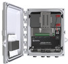
CRVW3 3-Channel Vibrating-Wire Datalogger The RF450 will be coupled with an NL201 device to enable the TCP/IP or internet connection. This allows the LoggerNet software to remotely drive the RF450 base radio over the TCP/IP connection. In this way, LoggerNet can be far away and out of radio range (at any location where reliable connectivity to the internet is available), and still use the base station's RF450 to communicate with the CRVW3 devices on the radio network. FIGURE 9-2. RF451 Network Base Station Configured for Remote LoggerNet Connectivity 9.3.1 Deploying CRVW3 End-node Stations, Confirming Radio Connectivity You should install individual radio-enabled CRVW3 devices at their field locations by following the instructions in Section 8.2, Field Deployment of the CRVW3. Ensure that the CRVW3-RF451 is configured as a Slave device using DevConfig. Do this from the Settings Editor tab in DevConfig. Choose the Radio tab. Now ensure that the Radio Operation Mode is set to Point to Multipoint Slave. Ensure that the Radio Enabled setting is set to True. The Radio ID setting should be a unique number for every CRVW3-RF451 being deployed. Every CRVW3 should use the same Frequency Key and the same Network ID. Press Apply if necessary. After the CRVW3 has been installed, powered, and configured, you should confirm that it can communicate over its radio (as described in Section 8.2.9, Validating CRVW3 Radio Operation, and Section 8.1.7, Validating Radio Connectivity in the Lab). Use a laptop running DevConfig and a portable RF450 device configured as the master radio to complete this step. From the CRVW3 location, confirm the line-of-sight path to the base station site. Install a directional/Yagi antenna (pn 14201) unless the distance to the base station is very short. Orient the Yagi antenna so that it points directly at the base station. 9.3.2 Base Station Installation and Validation Select a location for the base radio station that has good radio connectivity with all the CRVW3-RF451 stations, as well as TCP/IP Ethernet access. If the LoggerNet computer station will be co-located at the base station site, it will connect directly to the RF450 with a serial cable. Refer to Section 3.7 of the RF450 manual for details regarding the setup and configuration of the RF450 radio portion of the master/base station. s.campbellsci.com/documents/us/manuals/rf450.pdf Ensure that proper power, enclosure, grounding, and mounting options are available for permanently siting the base station. An omnidirectional antenna 44
-
 1
1 -
2
-
3
-
4
-
5
-
6
-
7
-
8
-
9
-
10
-
11
-
12
-
13
-
14
-
15
-
16
-
17
-
18
-
19
-
20
-
21
-
22
-
23
-
24
-
25
-
26
-
27
-
28
-
29
-
30
-
31
-
32
-
33
-
34
-
35
-
36
-
37
-
38
-
39
-
40
-
41
-
42
-
43
-
44
-
45
-
46
-
47
-
48
-
 49
49 -
 50
50 -
 51
51 -
 52
52 -
 53
53 -
 54
54 -
 55
55 -
 56
56 -
 57
57 -
 58
58 -
 59
59 -
60
-
61
-
62
-
63
-
64
-
65
-
66
-
67
-
68
-
69
-
70
-
71
-
72
-
73
-
74
-
75
-
76
-
77
-
78
-
79
-
80
-
81
-
82
-
83
-
84
-
85
-
86
-
87
-
88
-
89
-
90
-
91
-
92
-
93
-
94
-
95
-
96
-
97
-
98
-
99
-
100
-
101
-
102
-
103
-
104
-
105
-
106
-
107
-
108
-
109
-
110
-
111
-
112
 |
 |
