Campbell Scientific Vibrating CRVW3 3-Channel Vibrating-Wire Datalogger - Page 72
Base Station on the RF451 Network
 |
View all Campbell Scientific Vibrating manuals
Add to My Manuals
Save this manual to your list of manuals |
Page 72 highlights
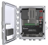
CRVW3 3-Channel Vibrating-Wire Datalogger communicates with more than one remote radio station. Consult the manual for the applicable radio device to obtain detailed instructions for setting up the radio portion of the base station. A CRVW3 device itself is not usually used as the base station in a CRVW3 network. This should only be done if a permanent USB cable connection can be maintained between the base CRVW3 and the LoggerNet computer. It is expected that this configuration will be used only rarely. Once the base station is set up and configured, you can use a temporary CRVW3 station located with you at the site to confirm operation of the base. You will also need to configure the LoggerNet station if it is co-located with the base station, or use a portable/laptop computer running LoggerNet to perform the validation. Configure LoggerNet to use the base station (see Section 10.7, LoggerNet Configuration), and confirm that you can connect to the temporary CRVW3 station and collect data from it. If CRVW3 end-node stations have already been deployed, LoggerNet can be configured to connect to and collect from those devices as well. Be sure to place the temporary CRVW3 more than 25 feet away from the base station antenna to avoid interference. 10.5.1 Base Station on the RF451 Network The RF450 radio should typically be used as the main component of the base station in an RF451 network. The RF450 will be configured as the master radio. Refer to Section 3.7 of the RF450 manual for details regarding the setup and configuration of the RF450 radio portion of the master/base station. s.campbellsci.com/documents/us/manuals/rf450.pdf. The base radio should connect to LoggerNet either through a serial cable or via a telemetry device such as the NL201, NL240, or LS300G. When using telemetry options, a serial cable is typically connected from the RS-232 port of the RF450 radio to the RS-232 port of the telemetry device. The telemetry device should usually be configured as a serial server. When using Campbell Scientific telemetry devices, the device can be configured as a PakBus router instead. Consult both the RF450 manual and the manual for your specific telemetry device for details about how to connect and configure these devices to work together. Once the base station is enabled via telemetry, LoggerNet will usually use TCP/IP to communicate with the base station. s.campbellsci.com/documents/us/manuals/nl200.pdf s.campbellsci.com/documents/us/manuals/nl240.pdf s.campbellsci.com/documents/us/manuals/ls300g.pdf When connecting the RF450 base radio directly to the LoggerNet computer, connect the serial cable to the RS-232 port of the RF450, and configure it with DevConfig as instructed in the RF450 manual. See Section 10.7.1, Physical Connection to the Base Station, for more information. 62
-
 1
1 -
2
-
3
-
4
-
5
-
6
-
7
-
8
-
9
-
10
-
11
-
12
-
13
-
14
-
15
-
16
-
17
-
18
-
19
-
20
-
21
-
22
-
23
-
24
-
25
-
26
-
27
-
28
-
29
-
30
-
31
-
32
-
33
-
34
-
35
-
36
-
37
-
38
-
39
-
40
-
41
-
42
-
43
-
44
-
45
-
46
-
47
-
48
-
49
-
50
-
51
-
52
-
53
-
54
-
55
-
56
-
57
-
58
-
59
-
60
-
61
-
62
-
63
-
64
-
65
-
66
-
 67
67 -
 68
68 -
 69
69 -
 70
70 -
 71
71 -
 72
72 -
 73
73 -
 74
74 -
 75
75 -
 76
76 -
 77
77 -
78
-
79
-
80
-
81
-
82
-
83
-
84
-
85
-
86
-
87
-
88
-
89
-
90
-
91
-
92
-
93
-
94
-
95
-
96
-
97
-
98
-
99
-
100
-
101
-
102
-
103
-
104
-
105
-
106
-
107
-
108
-
109
-
110
-
111
-
112
 |
 |
