Campbell Scientific Vibrating CRVW3 3-Channel Vibrating-Wire Datalogger - Page 68
Plan Validation with Others, 10.2.7.3 Hardware Procurement, 10.3 Deployment Strategy
 |
View all Campbell Scientific Vibrating manuals
Add to My Manuals
Save this manual to your list of manuals |
Page 68 highlights
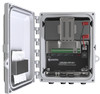
CRVW3 3-Channel Vibrating-Wire Datalogger radio link strength. For more information, see en.wikipedia.org/wiki/Fresnel_zone. 10.2.7.2 Plan Validation with Others It can be helpful to share your radio network plan with others. This process may uncover items that require additional planning. There may be others in your organization that have experience deploying and operating radio networks. Contact your local Campbell Scientific support representative to discuss your plan and any questions or concerns you may have with it. When using the Network Planner software, a saved *.NWP file can be provided to Campbell Scientific or others for review. Ensure that you have the right antenna types selected for each station. Mounting hardware may be needed for repeater stations and the base station. Review the items discussed in Section 8.2, Field Deployment of the CRVW3, for each station. 10.2.7.3 Hardware Procurement Using your network plan as a resource, contact your local Campbell Scientific representative to place an order for the required hardware. The ordering process brings a number of items into the discussion that are usually needed for typical deployments. 10.3 Deployment Strategy Once the hardware for your CRVW3 radio network arrives, it needs to be configured, validated, and deployed to the field. 10.3.1 Radio Network Lab Validation You should connect to each CRVW3 individually in the office or lab and configure it (See Section 8.1, Lab Connection and Configuration). However, you should also set up at least part of your radio network and validate it in the lab, if possible. Install and configure LoggerNet on a temporary or portable computer. Set up a base station, and confirm that it can communicate with a few CRVW3 stations. Set up a repeater station and ensure it works. Refer to Sections 10.4 through 10.7 for details about how this is done. NOTE Consider the use of the Network Planner when configuring your devices in the lab. After the devices are placed onto the canvas of the Network Planner software and settings are specified, then the software provides a way to connect to each device individually (in turn) and configure it. It operates in a similar manner to Device Configuration Utility, except that the settings are pushed into the device in a more automated manner. A checklist guides you through the process of isolating each device one at a time and connecting it to your computer to be configured. See Section 10.2, Planning the Radio Network, for more information about the Network Planner. 58
-
 1
1 -
2
-
3
-
4
-
5
-
6
-
7
-
8
-
9
-
10
-
11
-
12
-
13
-
14
-
15
-
16
-
17
-
18
-
19
-
20
-
21
-
22
-
23
-
24
-
25
-
26
-
27
-
28
-
29
-
30
-
31
-
32
-
33
-
34
-
35
-
36
-
37
-
38
-
39
-
40
-
41
-
42
-
43
-
44
-
45
-
46
-
47
-
48
-
49
-
50
-
51
-
52
-
53
-
54
-
55
-
56
-
57
-
58
-
59
-
60
-
61
-
62
-
 63
63 -
 64
64 -
 65
65 -
 66
66 -
 67
67 -
 68
68 -
 69
69 -
 70
70 -
 71
71 -
 72
72 -
 73
73 -
74
-
75
-
76
-
77
-
78
-
79
-
80
-
81
-
82
-
83
-
84
-
85
-
86
-
87
-
88
-
89
-
90
-
91
-
92
-
93
-
94
-
95
-
96
-
97
-
98
-
99
-
100
-
101
-
102
-
103
-
104
-
105
-
106
-
107
-
108
-
109
-
110
-
111
-
112
 |
 |
