Cisco ASR1002 Installation Guide - Page 10
Cisco ASR 1002 Router +24 VDC Power Supply
 |
UPC - 882658196416
View all Cisco ASR1002 manuals
Add to My Manuals
Save this manual to your list of manuals |
Page 10 highlights
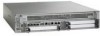
Cisco ASR 1002 Router Description Chapter 8 Cisco ASR 1002 Router Overview and Installation The Cisco ASR 1002 Router has two of the same type power supplies in power supply slot 0 and power supply slot 1. The power supply slot identifiers are zero (0) on the left side of the chassis rear and one (1) on the right side of the chassis rear. The power supply switch is a Standby switch and is not considered a disconnect. The +24 VDC power supply uses a spring-loaded terminal block. The input terminal block requires maximum 8AWG multi-strand wiring to support input current. The terminal block is compliant with safety agencies' guidelines and electrical requirements of the supply. Use the tie wraps to dress the input cable wires; there are two tie wrap tabs on the +24 VDC power supply. The +24 VDC power supply unit is secured into the system chassis with two captive screws mounted on the faceplate. Figure 8-8 shows the +24 VDC Power Supply for the Cisco ASR 1002 Router. Figure 8-8 Cisco ASR 1002 Router +24 VDC Power Supply 253164 0 7 56 OUTPUT INPUT FAN FAIL OK OK This unit might have more than one power supply connection. All connections must be removed to de-energize the unit. +27V DC INPUT +27V 32A 8 12349 1 +24 VDC terminal block 2 Positive (+) lead 3 Negative (-) lead 4 Ground (GND) lead 5 Power supply LEDs 7 OUTPUT INPUT FAN FAIL OK OK This unit might have more than one power supply connection. All connections must be removed to de-energize the unit. +27V DC INPUT +27V 32A 8 1 6 Standby/On switch 7 Captive fastener 8 Power supply tabs 9 +27 VDC INPUT label -- 8-10 Cisco ASR 1000 Series Aggregation Services Routers Hardware Installation Guide OL-13208-09
-
 1
1 -
2
-
3
-
4
-
 5
5 -
 6
6 -
 7
7 -
 8
8 -
 9
9 -
 10
10 -
 11
11 -
 12
12 -
 13
13 -
 14
14 -
 15
15 -
16
-
17
-
18
-
19
-
20
-
21
-
22
-
23
-
24
-
25
-
26
-
27
-
28
-
29
-
30
-
31
-
32
-
33
-
34
-
35
-
36
-
37
-
38
-
39
-
40
-
41
-
42
-
43
-
44
-
45
-
46
 |
 |