Cisco ASR1002 Installation Guide - Page 45
Cisco ASR 1002 Router Console Port Connection on Cisco Embedded ASR1000-RP1, Step 1
 |
UPC - 882658196416
View all Cisco ASR1002 manuals
Add to My Manuals
Save this manual to your list of manuals |
Page 45 highlights
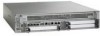
Chapter 8 Cisco ASR 1002 Router Overview and Installation Connecting a Terminal to the Cisco ASR1000-RP1 Console Port • One RJ-45 to RJ-45 crossover cable • One RJ-45 to DB-9 (female) adapter A crossover cable reverses pin connections from one end to the other. In other words, it connects pin 1 (at one end) to pin 8 (at the other end), pin 2 to pin 7, pin 3 to pin 6, and so on. You can identify a crossover cable by comparing the two modular ends of the cable. Hold the cable ends in your hand, side-by-side, with the tabs at the back. Ensure that the wire connected to the outside (left) pin of the left plug (pin 1) is the same color as the wire connected to the outside (right) pin of the right plug (pin 8). Use the following procedure to connect a video terminal to the console port on a route processor. Note Each Cisco ASR 1000 Series Route Processor 1 must have a console port connection (typically to a terminal server) if you are running a redundant configuration in the chassis. Step 1 Connect one end of the RJ-45 cables to the serial RJ-45 port (CON) on the Cisco embedded ASR1000-RP1 (see Figure 8-36). Figure 8-36 Cisco ASR 1002 Router Console Port Connection on Cisco Embedded ASR1000-RP1 12 A/L C/A 1 0 280285 A/L C/A ASR 1002 stat min pwr maj crit STAT QE0 QE1 QE2 QE3 BOOT CARRIER MTS LINK MGMT AUX CON PWR STAT SPA-4XOC3-POS 1 0 0 A/L C/A 1 A/L C/A 2 A/L C/A 3 A/L C/A STATUS 1 CON port connection 2 AUX port connection Step 2 Step 3 Step 4 Step 5 Step 6 Run the cable up and through the cable-management bracket and connect the other end of the RJ-45 cable to the RJ-45 adapter (see Figure 8-36). Connect the adapter to your video terminal to complete the cable connection. Power on your video terminal. Configure your video terminal to match the following default console port settings: • 9600 baud • 8 data bits • No parity generation or checking • 1 stop bit • No flow control Go to the "Connecting Cables" section on page 8-46 to continue the installation. OL-13208-09 Cisco ASR 1000 Series Aggregation Services Routers Hardware Installation Guide 8-45
-
 1
1 -
2
-
3
-
4
-
5
-
6
-
7
-
8
-
9
-
10
-
11
-
12
-
13
-
14
-
15
-
16
-
17
-
18
-
19
-
20
-
21
-
22
-
23
-
24
-
25
-
26
-
27
-
28
-
29
-
30
-
31
-
32
-
33
-
34
-
35
-
36
-
37
-
38
-
39
-
 40
40 -
 41
41 -
 42
42 -
 43
43 -
 44
44 -
 45
45 -
 46
46
 |
 |
