Cisco ASR1002 Installation Guide - Page 23
Attaching the Cable-Management Bracket - modules
 |
UPC - 882658196416
View all Cisco ASR1002 manuals
Add to My Manuals
Save this manual to your list of manuals |
Page 23 highlights
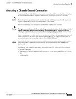
Chapter 8 Cisco ASR 1002 Router Overview and Installation Attaching the Cable-Management Bracket Step 5 Tighten all screws on each side to secure the chassis to the equipment rack (see Figure 8-15). Figure 8-15 Cisco ASR 1002 Router on a Four-Post Rack-Front and Rear Rack-Mounting 1 STATUS A/L C/A STATUS 2 ASR 1002 stat min pwr maj crit SPA-4XOC3-POS 0 0 A/L C/A A/L C/A 1 1 A/L C/A 2 2 A/L C/A 3 3 A/L C/A SPA-4XOC3-POS SPA-4XOC3-POS A/L C/A A/L C/A 0 A/L C/A 1 A/L C/A 2 A/L C/A 3 A/L C/A STATUS 280281 3 4 1 Rear rack equipment rail 2 Rear rack-mount bracket ear and holes 3 Front rack-mount bracket ear and holes 4 Front rack equipment rail Step 6 Use a level to verify that the tops of the two brackets are level, or use a measuring tape to verify that both brackets are the same distance from the top of the rack rails. This completes the procedure for installing the chassis in the rack. Proceed to the "Attaching the Cable-Management Bracket" section on page 8-23 to continue the installation. Attaching the Cable-Management Bracket The cable-management brackets mount to each rack-mount bracket on the chassis to provide cable-management to both sides of the chassis (parallel with card orientation). These brackets are screw mounted to the rack-mount brackets to allow easy installation and removal of cables. The cable-management brackets for the Cisco ASR 1002 Router contain one independent cable-management "U" type features with four screws and provides cable dressing of each card module slot. OL-13208-09 Cisco ASR 1000 Series Aggregation Services Routers Hardware Installation Guide 8-23
-
 1
1 -
2
-
3
-
4
-
5
-
6
-
7
-
8
-
9
-
10
-
11
-
12
-
13
-
14
-
15
-
16
-
17
-
 18
18 -
 19
19 -
 20
20 -
 21
21 -
 22
22 -
 23
23 -
 24
24 -
 25
25 -
 26
26 -
 27
27 -
 28
28 -
29
-
30
-
31
-
32
-
33
-
34
-
35
-
36
-
37
-
38
-
39
-
40
-
41
-
42
-
43
-
44
-
45
-
46
 |
 |
