Coby TV-DVD1390 Instruction Manual - Page 27
Component Audio/Video Input, To view the composite A/V device signal
 |
UPC - 716829971390
View all Coby TV-DVD1390 manuals
Add to My Manuals
Save this manual to your list of manuals |
Page 27 highlights
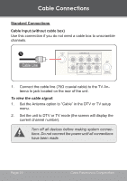
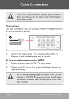
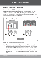
Cable Connections To view the composite A/V device signal: 1. Turn on the A/V device. 2. Set the unit to AV mode (the screen will display "AV"). Turn off all devices before making system connections. Do not connect the power until all connections have been made. Component Audio/Video Input Use this connection to display optional A/V devices on the unit. A/V devices may include DVD players, cable/satellite receivers, camcorders, or game consoles that are equipped with component audio/video output jacks. Device with Component A/V Output AUDIO OUTPUT COMPONENT VIDEO OUTPUT Rear Component Video Jacks Y Cb Cr WHITE RED GREEN BLUE RED RED WHITE GREEN BLUE RED 1 2 Component Video Cable (optional) www.cobyusa.com Page 27
-
 1
1 -
2
-
3
-
4
-
5
-
6
-
7
-
8
-
9
-
10
-
11
-
12
-
13
-
14
-
15
-
16
-
17
-
18
-
19
-
20
-
21
-
 22
22 -
 23
23 -
 24
24 -
 25
25 -
 26
26 -
 27
27 -
 28
28 -
 29
29 -
 30
30 -
 31
31 -
 32
32 -
33
-
34
-
35
-
36
-
37
-
38
-
39
-
40
-
41
-
42
-
43
-
44
-
45
-
46
-
47
-
48
-
49
-
50
-
51
-
52
-
53
-
54
-
55
-
56
-
57
-
58
-
59
-
60
-
61
-
62
-
63
-
64
-
65
-
66
-
67
-
68
-
69
-
70
-
71
-
72
-
73
-
74
-
75
-
76
 |
 |

www.cobyusa.com
Page ±
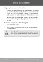
To view the composite A/V device signal:
Turn on the A/V device.
Set the unit to AV mode (the screen will display “AV”).
Turn off all devices before making system connec-
tions. Do not connect the power until all connections
have been made.
Component Audio/Video Input
Use this connection to display optional A/V devices on the unit.
A/V devices may include DVD players, cable/satellite receivers,
camcorders, or game consoles that are equipped with component
audio/video output jacks.
1
2
Component Video Cable (optional)
Device with Component
A/V Output
Rear Component Video Jacks
RED
RED
WHITE
BLUE
GREEN
RED
RED
WHITE
BLUE
GREEN
AUDIO
OUTPUT
COMPONENT VIDEO
OUTPUT
Y
Cb
Cr
1.
2.
Cable Connections