Compaq nc6120 HP Compaq nx6110, nc6110, nx6120 and nc6120 Notebook PCs - Maint - Page 109
Description, of Screws Removed
 |
View all Compaq nc6120 manuals
Add to My Manuals
Save this manual to your list of manuals |
Page 109 highlights
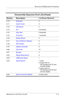
Removal and Replacement Procedures Disassembly Sequence Chart (Continued) Section 6.10 6.11 6.12 6.13 6.14 6.15 6.16 6.17 6.18 6.19 6.20 6.21 6.22 6.23 6.24 Description Keyboard Switch Cover LED Board Fan Heat Sink Processor Modem Board Internal Memory Module RTC Battery Display Assembly Top Cover Speaker Digital Media Board USB/Audio Board System Board 6.25 Serial Connector Module # of Screws Removed 2 2 4 2 loosened 4 loosened 1 loosened 2 0 0 6 15 4 0 1 1 screw 4 screw locks on HP Compaq nc6110 and nc6120 models 2 screw locks on HP Compaq nx6110 and nx6120 models 2 screw locks Maintenance and Service Guide 6-3
-
 1
1 -
2
-
3
-
4
-
5
-
6
-
7
-
8
-
9
-
10
-
11
-
12
-
13
-
14
-
15
-
16
-
17
-
18
-
19
-
20
-
21
-
22
-
23
-
24
-
25
-
26
-
27
-
28
-
29
-
30
-
31
-
32
-
33
-
34
-
35
-
36
-
37
-
38
-
39
-
40
-
41
-
42
-
43
-
44
-
45
-
46
-
47
-
48
-
49
-
50
-
51
-
52
-
53
-
54
-
55
-
56
-
57
-
58
-
59
-
60
-
61
-
62
-
63
-
64
-
65
-
66
-
67
-
68
-
69
-
70
-
71
-
72
-
73
-
74
-
75
-
76
-
77
-
78
-
79
-
80
-
81
-
82
-
83
-
84
-
85
-
86
-
87
-
88
-
89
-
90
-
91
-
92
-
93
-
94
-
95
-
96
-
97
-
98
-
99
-
100
-
101
-
102
-
103
-
 104
104 -
 105
105 -
 106
106 -
 107
107 -
 108
108 -
 109
109 -
 110
110 -
 111
111 -
 112
112 -
 113
113 -
 114
114 -
115
-
116
-
117
-
118
-
119
-
120
-
121
-
122
-
123
-
124
-
125
-
126
-
127
-
128
-
129
-
130
-
131
-
132
-
133
-
134
-
135
-
136
-
137
-
138
-
139
-
140
-
141
-
142
-
143
-
144
-
145
-
146
-
147
-
148
-
149
-
150
-
151
-
152
-
153
-
154
-
155
-
156
-
157
-
158
-
159
-
160
-
161
-
162
-
163
-
164
-
165
-
166
-
167
-
168
-
169
-
170
-
171
-
172
-
173
-
174
-
175
-
176
-
177
-
178
-
179
-
180
-
181
-
182
-
183
-
184
-
185
-
186
-
187
-
188
-
189
-
190
-
191
-
192
-
193
-
194
-
195
-
196
-
197
-
198
-
199
-
200
-
201
-
202
-
203
-
204
-
205
-
206
-
207
-
208
-
209
-
210
-
211
-
212
-
213
-
214
-
215
-
216
-
217
-
218
-
219
-
220
-
221
-
222
-
223
-
224
-
225
-
226
-
227
-
228
-
229
-
230
-
231
-
232
-
233
-
234
-
235
-
236
-
237
 |
 |
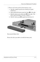
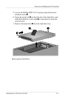
Removal and Replacement Procedures
Maintenance and Service Guide
6–3
Section
Description
# of Screws Removed
6.10
Keyboard
2
6.11
Switch Cover
2
6.12
LED Board
4
6.13
Fan
2 loosened
6.14
Heat Sink
4 loosened
6.15
Processor
1 loosened
6.16
Modem Board
2
6.17
Internal Memory Module
0
6.18
RTC Battery
0
6.19
Display Assembly
6
6.20
Top Cover
15
6.21
Speaker
4
6.22
Digital Media Board
0
6.23
USB/Audio Board
1
6.24
System Board
1 screw
4 screw locks on
HP Compaq nc6110 and
nc6120 models
2 screw locks on
HP Compaq nx6110 and
nx6120 models
6.25
Serial Connector Module
2 screw locks
Disassembly Sequence Chart
(Continued)