Compaq nc6120 HP Compaq nx6110, nc6110, nx6120 and nc6120 Notebook PCs - Maint - Page 235
PC Card slots, System Restore
 |
View all Compaq nc6120 manuals
Add to My Manuals
Save this manual to your list of manuals |
Page 235 highlights
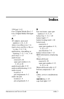
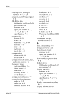
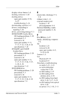
Index spare part numbers 4-13, 4-18, 4-22, 4-23, 4-26 specifications 7-9, 7-10, 7-12, 7-14 P packing precautions 5-5 parallel port location 1-13 pin assignments A-4 PC Card eject buttons 1-11 PC Card slot space saver 4-14 PC Card slots 1-11 plastic parts 5-2 pointing device, troubleshooting 2-25 pointing stick 1-19 pointing stick board, spare part number 4-28, 6-39 pointing stick buttons 1-19 power button 1-16 power connector 1-13 power cord set requirements B-2 spare part numbers 4-20, 4-21 power light 1-7, 1-16 power management features 1-5 power, troubleshooting 2-8 processor removal 6-30 spare part numbers 4-7, 4-23, 4-24, 6-30 product name and number, computer 3-2 R rear components 1-10 reinstalling or repairing software 3-12, 3-14, 3-16 See also System Restore removal/replacement preliminaries 5-1 procedures 6-1 restore points 3-9 right-side components 1-8 RJ-11 connector module and cable illustrated 4-15 removal 6-53 RJ-11 jack location 1-11 pin assignments A-7 RJ-45 jack location 1-11 pin assignments A-8 ROM downloading and installing 3-4 finding version information 3-1 obtaining updates 3-1 ROMPaq 3-3 RTC battery illustrated 4-14 removal 6-35 S Screw Kit contents C-1 spare part number 4-19, C-1 Index-6 Maintenance and Service Guide
-
 1
1 -
2
-
3
-
4
-
5
-
6
-
7
-
8
-
9
-
10
-
11
-
12
-
13
-
14
-
15
-
16
-
17
-
18
-
19
-
20
-
21
-
22
-
23
-
24
-
25
-
26
-
27
-
28
-
29
-
30
-
31
-
32
-
33
-
34
-
35
-
36
-
37
-
38
-
39
-
40
-
41
-
42
-
43
-
44
-
45
-
46
-
47
-
48
-
49
-
50
-
51
-
52
-
53
-
54
-
55
-
56
-
57
-
58
-
59
-
60
-
61
-
62
-
63
-
64
-
65
-
66
-
67
-
68
-
69
-
70
-
71
-
72
-
73
-
74
-
75
-
76
-
77
-
78
-
79
-
80
-
81
-
82
-
83
-
84
-
85
-
86
-
87
-
88
-
89
-
90
-
91
-
92
-
93
-
94
-
95
-
96
-
97
-
98
-
99
-
100
-
101
-
102
-
103
-
104
-
105
-
106
-
107
-
108
-
109
-
110
-
111
-
112
-
113
-
114
-
115
-
116
-
117
-
118
-
119
-
120
-
121
-
122
-
123
-
124
-
125
-
126
-
127
-
128
-
129
-
130
-
131
-
132
-
133
-
134
-
135
-
136
-
137
-
138
-
139
-
140
-
141
-
142
-
143
-
144
-
145
-
146
-
147
-
148
-
149
-
150
-
151
-
152
-
153
-
154
-
155
-
156
-
157
-
158
-
159
-
160
-
161
-
162
-
163
-
164
-
165
-
166
-
167
-
168
-
169
-
170
-
171
-
172
-
173
-
174
-
175
-
176
-
177
-
178
-
179
-
180
-
181
-
182
-
183
-
184
-
185
-
186
-
187
-
188
-
189
-
190
-
191
-
192
-
193
-
194
-
195
-
196
-
197
-
198
-
199
-
200
-
201
-
202
-
203
-
204
-
205
-
206
-
207
-
208
-
209
-
210
-
211
-
212
-
213
-
214
-
215
-
216
-
217
-
218
-
219
-
220
-
221
-
222
-
223
-
224
-
225
-
226
-
227
-
228
-
229
-
 230
230 -
 231
231 -
 232
232 -
 233
233 -
 234
234 -
 235
235 -
 236
236 -
 237
237
 |
 |