Compaq nc6120 HP Compaq nx6110, nc6110, nx6120 and nc6120 Notebook PCs - Maint - Page 131
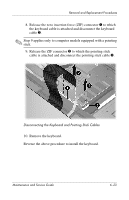
and lift up until the cover, disengages from the computer.
 |
View all Compaq nc6120 manuals
Add to My Manuals
Save this manual to your list of manuals |
Page 131 highlights
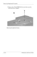
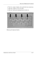
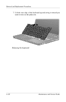
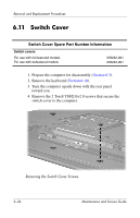
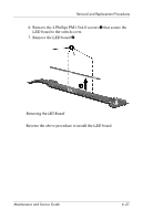
Removal and Replacement Procedures 5. Turn the computer display-side up with front toward you. 6. Open the computer as far as possible. 7. Disconnect the LED board cable 1 from the system board. 8. Insert a flat-bladed screwdriver into the four notches 2 on the front edge of the switch cover 3 and lift up until the cover disengages from the computer. 9. Remove the switch cover. Removing the Switch Cover Reverse the above procedure to install the switch cover. Maintenance and Service Guide 6-25
-
 1
1 -
2
-
3
-
4
-
5
-
6
-
7
-
8
-
9
-
10
-
11
-
12
-
13
-
14
-
15
-
16
-
17
-
18
-
19
-
20
-
21
-
22
-
23
-
24
-
25
-
26
-
27
-
28
-
29
-
30
-
31
-
32
-
33
-
34
-
35
-
36
-
37
-
38
-
39
-
40
-
41
-
42
-
43
-
44
-
45
-
46
-
47
-
48
-
49
-
50
-
51
-
52
-
53
-
54
-
55
-
56
-
57
-
58
-
59
-
60
-
61
-
62
-
63
-
64
-
65
-
66
-
67
-
68
-
69
-
70
-
71
-
72
-
73
-
74
-
75
-
76
-
77
-
78
-
79
-
80
-
81
-
82
-
83
-
84
-
85
-
86
-
87
-
88
-
89
-
90
-
91
-
92
-
93
-
94
-
95
-
96
-
97
-
98
-
99
-
100
-
101
-
102
-
103
-
104
-
105
-
106
-
107
-
108
-
109
-
110
-
111
-
112
-
113
-
114
-
115
-
116
-
117
-
118
-
119
-
120
-
121
-
122
-
123
-
124
-
125
-
 126
126 -
 127
127 -
 128
128 -
 129
129 -
 130
130 -
 131
131 -
 132
132 -
 133
133 -
 134
134 -
 135
135 -
 136
136 -
137
-
138
-
139
-
140
-
141
-
142
-
143
-
144
-
145
-
146
-
147
-
148
-
149
-
150
-
151
-
152
-
153
-
154
-
155
-
156
-
157
-
158
-
159
-
160
-
161
-
162
-
163
-
164
-
165
-
166
-
167
-
168
-
169
-
170
-
171
-
172
-
173
-
174
-
175
-
176
-
177
-
178
-
179
-
180
-
181
-
182
-
183
-
184
-
185
-
186
-
187
-
188
-
189
-
190
-
191
-
192
-
193
-
194
-
195
-
196
-
197
-
198
-
199
-
200
-
201
-
202
-
203
-
204
-
205
-
206
-
207
-
208
-
209
-
210
-
211
-
212
-
213
-
214
-
215
-
216
-
217
-
218
-
219
-
220
-
221
-
222
-
223
-
224
-
225
-
226
-
227
-
228
-
229
-
230
-
231
-
232
-
233
-
234
-
235
-
236
-
237
 |
 |
Removal and Replacement Procedures
Maintenance and Service Guide
6–25
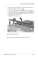
5. Turn the computer display-side up with front toward you.
6. Open the computer as far as possible.
7. Disconnect the LED board cable
1
from the system board.
8.
Insert a flat-bladed screwdriver into the four notches
2
on the
front edge of the switch cover
3
and lift up until the cover
disengages from the computer.
9. Remove the switch cover.
Removing the Switch Cover
Reverse the above procedure to install the switch cover.