Craftsman 18178 Operation Manual - Page 3
Description, Air Supply Line - framing nails
 |
View all Craftsman 18178 manuals
Add to My Manuals
Save this manual to your list of manuals |
Page 3 highlights
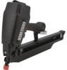
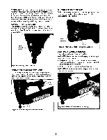
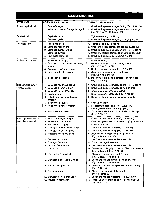
DESCRIPTION The Craftsman Full Head Framing Nailer drives nailsfrom .113" to .131" diameter and from 2" to 3'h" long. Magazine is angled at 21 ° for nailing in tight spotssuch as when toenailing. High strength magnesium body and aluminum components are lightweight and durable. Safety feature disables tool unless contact trip is pressed against workpiece. Sequential trigger switch allows selection of rapid-tire or single-firemode. Contact trip can be adjusted for setting nail depth. Pusher mechanism supports shorter fasteners to prevent jamming. Plastic protector on the end of contact trip prevents marring of workpiece. Large capacity,end loading magazine makes it easy to load up to 70 stick nails at a time. Tool drives straight,screw, and ring shank nails.Exhaust deflector can be rotated 360°. The Angle Framing Nailer is excellent for truss making, framing, sheathing, sub-flooringand decking. SPECIFICATIONS Capacity Nail diameter 65 nails (3'/2"),70 nails (2") 113 to .131" Nail lengths 2 to 3'h" Operating pressure Air inlet 70 1o 110 PSI '/4" N.RT. Length Height Width 22V," 14'/2" 5" Weight 7.6 Ibs. NAILS 18375 18376 18377 18378 8 penny, .113" diameter x 23/", long 10 penny, .131" diameter x 3" long 12 penny, .131" diameter x 3'/," long 16 penny, .131" diameter x 3V="long AIR SUPPLY LINE Refer to Figure 1. DANGER: Do not usa oxygen, carbon dioxide, high-pressure compressed gas or bottled gases as the power source for this tool. The tool will explode and serious personal injury could result. • The air tool operates on compressed air at pressures from 70 to 110 PSI. • Never connect the tool to air pressure which could potentially exceed 200 PSI. Use only clean, dry, regulated air within rated range as marked on tool, Air Denvery Required: 2.21 SCFM @ 90 PSI (30 shots per minute). WARNING: Keep hands and body away from discharge area of tool when connecting air supply. Always disconnect tool from air supply when servicing or adjusting tool and when tool is not in use. • Air operated tools require clean, dry, lubricated compressed air to ensure top performance, low maintenance and long life. • Dirt and abrasive materials present in all air lines will damage tool O-rings, valves and cylinders. • Moisture will reduce tool performance and life if not removed from compressed air. A filter-regulator-lubricator system is required and shouldbe located as close to tool as possible.A distance of less than 15 feet is recommended. Lubricator is not required for oilless tools. • Keep air filter clean. A dirty filter will reduce the air pressure to the tool causing a reduction in power and efficiency. • The air supply system must be able to provide air pressure of 70 to 110 pounds per square inch at tool. • All hoses and pipes in the air supply system must be clean and free of moisture and foreign particles. Hoses must be rated for a maximum working pressure of 150 PSI or 150% of maximum system pressure, whichever is greater. • Do not mount swivel connector in air supply line. • The air pressure should be properly regulated. • Different workpiece materials and different fastener lengths will require different operating pressure. • Be sure all connections in air supply system are sealed to prevent air loss. • Never connect a female quick-disconnect couplingto the tool side of air line connection. A male, free-flow coupling should be connected to the tool side of air line connection (see Figure 1). WARNING: The female coupling provides a seal preventing loss of compressed air from compressor tank when disconnected from male coupling. If connected to tool side of air supply, the female coupling could seal a compressed air charge in the tool which could discharge if the tool trigger is actuated. Male Connector \ Figure 1 - Air Supply Line LOADING Refer to Figures 2, 3 & 4, page 4. WARNING: Disconnect tool from air supply. Do not load tool until you are ready to use it. Do not pull trigger or depress contact trip while loading tool. Always load with nose of tool pointing away from you and others. Always wear safety goggles that comply with United States ANSI Z87.1. NOTE: For best results, use Sears fasteners only. 3
-
 1
1 -
 2
2 -
 3
3 -
 4
4 -
 5
5 -
 6
6 -
 7
7 -
 8
8 -
 9
9 -
10
-
11
-
12
-
13
-
14
-
15
-
16
-
17
-
18
-
19
-
20
 |
 |
