Creative 70EM896106000 Owners Manual - Page 16
m Owners - Install the 0202 Daughter Card, Connecting the MicroDock, Daughter - pci
 |
UPC - 054651126893
View all Creative 70EM896106000 manuals
Add to My Manuals
Save this manual to your list of manuals |
Page 16 highlights
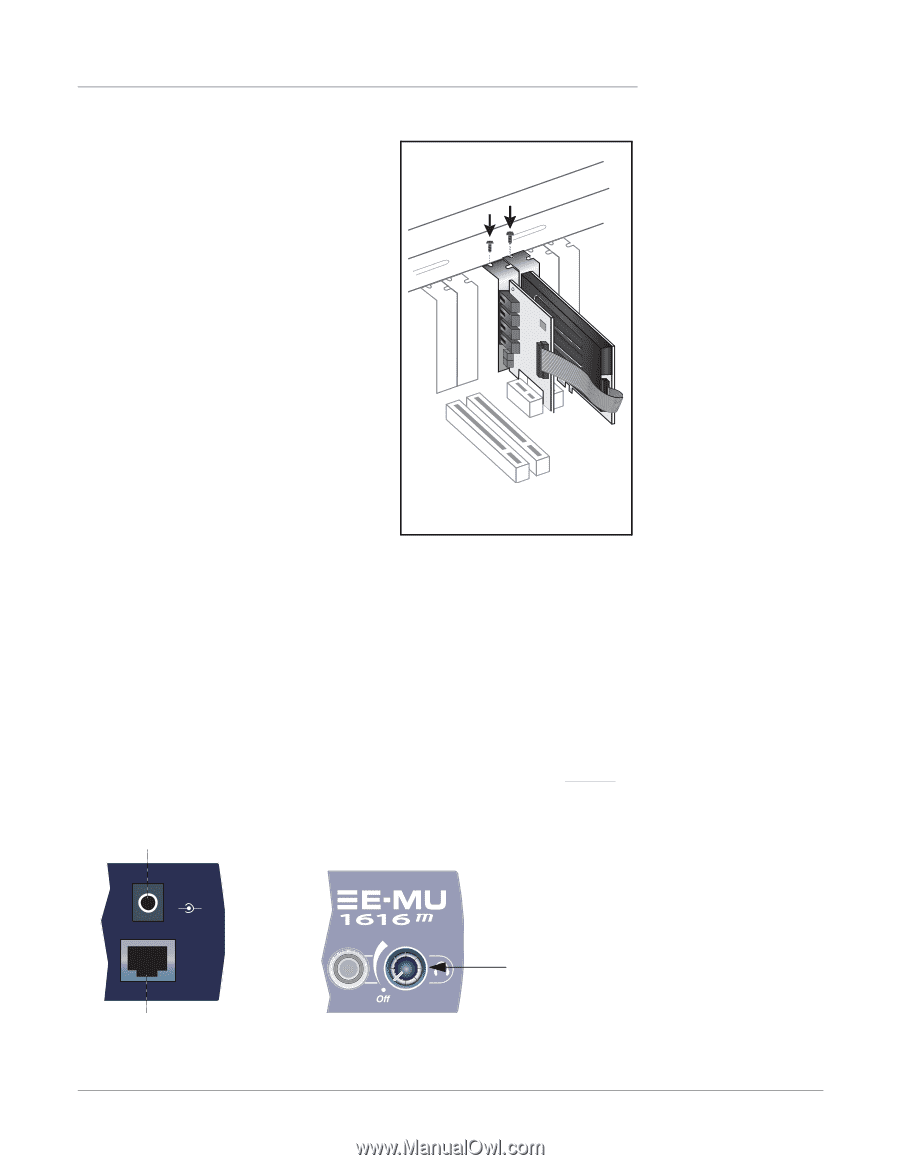
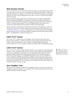
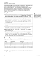
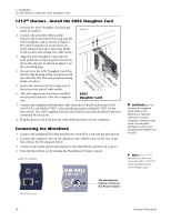
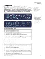
2 - Installation 1212m Owners - Install the 0202 Daughter Card 1212m Owners - Install the 0202 Daughter Card 1. Unwrap the 0202 Daughter Card and get ready to install it. Figure 3 2. Connect the provided ribbon cable between the E-MU 1010 PCIe card and the 0202 Daughter card as shown in figure 3. The cable is keyed so it cannot be incorrectly inserted. Seat the connectors firmly in the sockets and arrange the cable neatly. 3. Align the 0202 Daughter Card with the back panel slot and press gently but firmly down into the slot as shown in figure 2 on the preceding page. 4. Do not force the 0202 Daughter Card into the slot. The bottom of the card does not fit into the PCIe slot. The rear panel mounting holds it in place. 5. Secure the card into the slot using one of the screws you placed aside earlier. PCI Slots PCIePxC1Ie x1 6. After all components have been installed and securely fastened, close the computer case. 0202 Daughter Card 7. Connect the supplied network-type cable from the 10 BaseT jack on the E-MU 1010 PCIe card labeled "EDI" to the matching connector labeled "EDI" on the MicroDock. The cable supplied with the MicroDock is specially shielded to prevent unwanted RF emissions. 8. Plug the power cord back into the wall outlet and turn on your computer. Connecting the MicroDock 1. Connect the supplied EDI cable between the 1010 PCIe Card and the MicroDock. 2. Connect the supplied +48 volt DC adapter to the +48VDC jack on the rear of the MicroDock. See the diagram below. 3. Connect your audio inputs and outputs to the MicroDock as shown on page 25. 4. Turn the MicroDock on by turning the Headphone Volume control. +48V DC Adapter 48 VDC + - CAUTION: Do not connect the supplied CAT5 cable to the Ethernet or network connector on your computer. Doing so may result in permanent damage to either your computer, the E-MU 1010 or both. Note: The 1616m MicroDocks cannot be used with older 1010 PCI cards identified by the 1394 FireWire port. EDI 1010 PCIe Card The Headphone Volume Control is the Power Switch. 16 Creative Professional
-
 1
1 -
2
-
3
-
4
-
5
-
6
-
7
-
8
-
9
-
10
-
 11
11 -
 12
12 -
 13
13 -
 14
14 -
 15
15 -
 16
16 -
 17
17 -
 18
18 -
 19
19 -
 20
20 -
 21
21 -
22
-
23
-
24
-
25
-
26
-
27
-
28
-
29
-
30
-
31
-
32
-
33
-
34
-
35
-
36
-
37
-
38
-
39
-
40
-
41
-
42
-
43
-
44
-
45
-
46
-
47
-
48
-
49
-
50
-
51
-
52
-
53
-
54
-
55
-
56
-
57
-
58
-
59
-
60
-
61
-
62
-
63
-
64
-
65
-
66
-
67
-
68
-
69
-
70
-
71
-
72
-
73
-
74
-
75
-
76
-
77
-
78
-
79
-
80
-
81
-
82
-
83
-
84
-
85
-
86
-
87
-
88
-
89
-
90
-
91
-
92
-
93
-
94
-
95
-
96
-
97
-
98
-
99
-
100
-
101
-
102
-
103
-
104
-
105
-
106
-
107
-
108
-
109
-
110
-
111
-
112
-
113
-
114
-
115
-
116
-
117
-
118
-
119
-
120
-
121
-
122
-
123
-
124
-
125
-
126
-
127
-
128
-
129
-
130
-
131
-
132
 |
 |