Cub Cadet BC 210 BC 210 Operator's Manual
Cub Cadet BC 210 Manual
 |
View all Cub Cadet BC 210 manuals
Add to My Manuals
Save this manual to your list of manuals |
Cub Cadet BC 210 manual content summary:
- Cub Cadet BC 210 | BC 210 Operator's Manual - Page 1
BC210 2-Cycle Gasoline Trimmer / Brushcutter Operator's Manual English - Page 1 Français - Page 6 Removing Unit From Carton 1 Remove all contents from carton. Assemble The Unit (4) Screws 40:1 2 Remove cap from lower boom. Push cutting attachment into coupler. Turn coupler knob clockwise to - Cub Cadet BC 210 | BC 210 Operator's Manual - Page 2
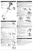
teens under the age of 15 must not use the unit, except for teens guided by an adult. • All guards and safety attachments must be installed properly before operating the unit. • Inspect the unit before use. Replace damaged parts. Check for fuel leaks. Make sure all fasteners are in place and secure - Cub Cadet BC 210 | BC 210 Operator's Manual - Page 3
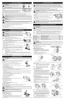
: To avoid serious personal injury, the cutting attachment shield MUST be in place at all times while operating the unit as a trimmer. Locking Rod Fig. 15 Fig. 16 OIL AND FUEL INFORMATION OIL AND FUEL MIXING INSTRUCTIONS Old and/or improperly mixed fuel are the main reasons for the unit not - Cub Cadet BC 210 | BC 210 Operator's Manual - Page 4
to stop before removing materials wrapped around the blade shaft. MAINTENANCE AND REPAIR INSTRUCTIONS MAINTENANCE SCHEDULE WARNING: To prevent serious injury, never perform maintenance or repairs with unit running. Always service and repair a cool unit. Disconnect the spark plug wire to ensure - Cub Cadet BC 210 | BC 210 Operator's Manual - Page 5
service dealer should make carburetor adjustments. Air Filter Cover Fig. 34 Hooks WARNING: The cutting attachment will spin during idle speed adjustments. Wear protective clothing and observe all safety instructions to prevent serious personal injury. If, after checking the fuel mixture - Cub Cadet BC 210 | BC 210 Operator's Manual - Page 6
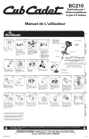
BC210 Désherbeuse / débroussailleuse à gaz à 2-temps Manuel de L'utilisateur English - Page 1 Retirer remplacement, appelez le 1-877-282-8684 ou rendez-vous chez un distributeur agréé. Pour les instructions d'installation d'un fil de coupe simple ou de remplacement de la bobine, reportez-vous à - Cub Cadet BC 210 | BC 210 Operator's Manual - Page 7
TECHNIQUE TABLE DES MATIÈRES Service technique 7 Consignes de sécurit 7 Familiarisez-vous avec votre appareil 8 Instructions de montage 8 Informations sur l'huile et le carburant 8 Instructions de démarrage et d'arrêt 9 Mode d'emploi 9 Entretien et réparations 9 Nettoyage et entreposage - Cub Cadet BC 210 | BC 210 Operator's Manual - Page 8
coupe lame de débroussaillage INSTRUCTIONS DE MONTAGE INSTALLATION ET operator's body when the unit is held in the operating sol ou sur un établi. Renfoncement-guide Fig. 2 Corps de l'arbre lame Trou de guidage Écrou Lame de coupe Support du protecteur Pas de guidage Bague de l'arbre de - Cub Cadet BC 210 | BC 210 Operator's Manual - Page 9
démarreur Fig. 18 Position de départ 6. Mettez le levier d'étrangleur en head parallel to the ground. • Do not force the cutting head thrown away from the operator. • Slowly move the only when grass and weeds are dry. • Fig. 21). Fig. 21 INSTRUCTIONS D'UTILISATION UTILISATION DE LA LAME - Cub Cadet BC 210 | BC 210 Operator's Manual - Page 10
à haut régime pendant une minute pour se réchauffer. Voir les Instructions de démarrage et d'arrêt. Fig. 35 2. Relâchez la ) Mécanisme de coupe Lame de coupe à 4 dents, Bump Head™ Diamètre du fil 2,67 mm (0,105 po) Diamètre ÊTS DE MOTEUR TANDIS QU'EN SERVICE CAUSE La protection de survitesse de - Cub Cadet BC 210 | BC 210 Operator's Manual - Page 11
BC210 Recortador / Cortamalezas de 2 Tiempos a Gasolina Manual del Operador English - Page 1 Sacar la la sección Cambiar la línea de corte de este manual. *Éste es asistir a la recarga de Splitline® solamente. Estas instrucciones no son parte de las instrucciones de asamblea rápidas. La línea - Cub Cadet BC 210 | BC 210 Operator's Manual - Page 12
opere. Mantenga un agarre firme sobre ambas manijas. • Mantenga las manos, la cara y los pies alejados de todas las partes hojas, exceso de grasa o acumulación de carbón. OTROS AVISOS DE SEGURIDAD • Nunca almacene • INDICADOR DE ACEITE Consulte el manual del operador para obtener información acerca - Cub Cadet BC 210 | BC 210 Operator's Manual - Page 13
accesorio de corte Cuchilla de corte de línea ASSEMBLY INSTRUCTIONS Instale el protector accesorio de corte cuando use la unidad ADVERTENCIA : Antes de comenzar a usar este accesorio, lea y comprenda el manual que viene con el accesorio. Siga toda la información de seguridad contenida en - Cub Cadet BC 210 | BC 210 Operator's Manual - Page 14
lentamente para evitar lesionarse con el rociado del combustible. No opere nunca la unidad sin la tapa del combustible firmemente colocada donde es difícil ver el material que está cortando. • Corte girando la parte superior de su cuerpo de izquierda a derecha. • Suelte siempre el gatillo del - Cub Cadet BC 210 | BC 210 Operator's Manual - Page 15
El motor podría dañarse si penetran pequeñas partículas en el cilindro. 3. Cambie las bujías ) Mecanismo de corte Cuchilla de corte de 4 dientes, Bump Head™ Diámetro de la línea de corte 2,67 mm (0,105 manual se basan en la información más reciente disponible en el momento de impresión del manual - Cub Cadet BC 210 | BC 210 Operator's Manual - Page 16
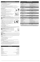
Service Department of Cub Cadet. This limited warranty does not provide coverage in the following cases: A. Tune-ups - Spark Plugs, Carburetor Adjustments, Filters B. Wear items - Bump Knobs, Outer Spools, Cutting Line, Inner Reels, Starter Pulley, Starter Ropes, Drive Belts, Saw Chains, Guide
-
 1
1 -
 2
2 -
 3
3 -
 4
4 -
 5
5 -
 6
6 -
 7
7 -
8
-
9
-
10
-
11
-
12
-
13
-
14
-
15
-
16
 |
 |
769-07384 P00
12/11
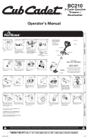
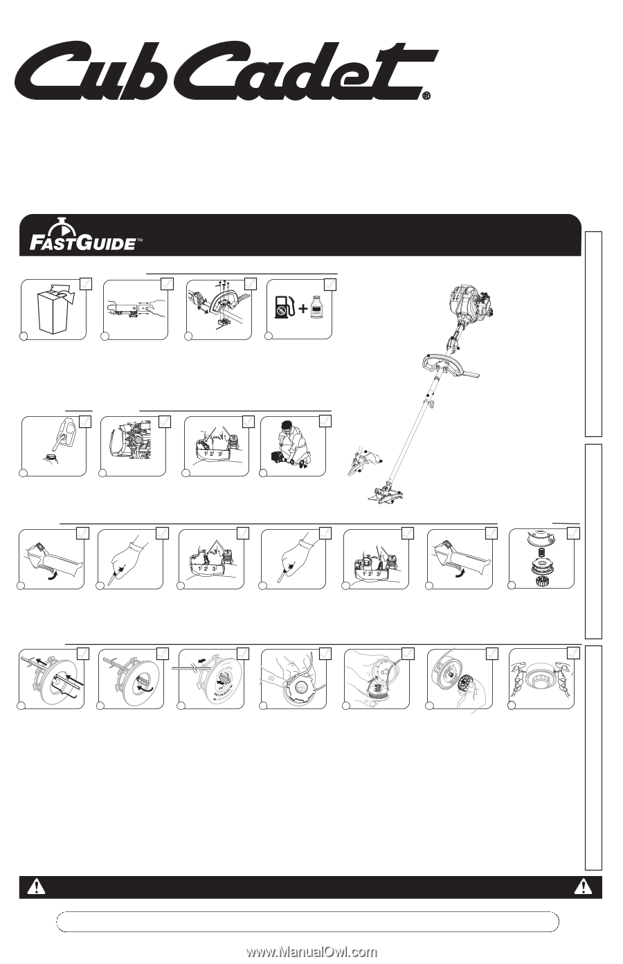
IMPORTANT: READ OPERATOR’S MANUAL THOROUGHLY AND FOLLOW THE SAFE OPERATION PRACTICES BEFORE OPERATING THE UNIT.
Removing Unit From Carton
Assemble The Unit
Starting The Unit
Remove cap from lower
boom. Push cutting
attachment into coupler.
Turn coupler knob clockwise
to tighten.
Assemble The Unit
Mix thoroughly in separate
fuel can:
– 3.2 fl. oz. of 2-cycle
engine oil
– 1 gallon of unleaded
gasoline
NOTE:
Do not mix directly in
fuel tank.
Place unit on a level surface.
Fill fuel tank.
Press
primer bulb
10 times
,
or until fuel is visible
Crouch in starting position.
SQUEEZE
and
HOLD
throttle for
ALL
further
steps.
Pull rope
5 times
.
Move choke lever to
Position 2
and squeeze
throttle.
Pull rope
3-5 times
to start
engine. Run unit for
30-60
seconds
to warm up.
Continue to squeeze
throttle.
Move choke lever
to
Position 3
.
1
1
Remove all contents from
carton.
4
5
6
1
8
9
2
Place the D-handle over the
shaft housing and onto the
bottom clamp. Place it a
minimum of
6 inches
from the
end of the shaft grip.
Move
choke lever to
Position 1
.
Continue to squeeze
throttle.
Run unit for an
additional
60 seconds
to
complete warm-up. Unit
may be used during this
time.
7
3
Starting The Unit
10
11
12
13
14
Primer
Bulb
10 X
5 X
3-5 X
Choke Lever
Starter Rope
Fuel Cap
Throttle Control
Blade Shield /
Shield Mount
Brush Blade
Cutting
Head Shield
Cutting
Head
Line
Cutting
Blade
On/ Off Switch
D-Handle
Rapid-link™
Need Help?
Call 1-877-282-8684
DIDN’T START?
Repeat these instructions.
IF
engine fails to start after 2 attempts,
move choke lever to position 3 and pull
the starter rope until engine starts
IF
unit still fails to start, refer to the
operator’s manual for additional starting
and troubleshooting information
1 Gallon
3.2 oz
40:1
Choke Lever
Choke Lever
Min. 6"
Tools Required
• Flat blade screwdriver
• T-25 Tox screwdriver
• Locking Rod
• 13 mm closed-end
or socket wrench
Bottom
Clamp
(4) Screws
Unscrew bump knob
clockwise. Remove
inner reel and spring.
Insert
10'
of 0.105"SplitLine
®
through hole in top of reel.
Pull most of line through hole
until 3"-4" remains.
Bend short end and push it
into the other hole. Pull tight.
Wind
line tightly in direction
of arrow. Split
other end of
SplitLine
®
back 6"-7".
Push
6"-7" ends into
the holding slots.
Insert lines through eyelets in
spool. Insert spring and reel
into spool.
1
1
Hold the inner reel in place.
Tighten Bump Knob
counterclockwise
.
Reloading The Line*
3
4
5
6
7
Pull lines firmly to release
from holding slots.
1
8
Reloading The Line
2
For replacement line, call
1-877-282-8684
or go to
an authorized service dealer.
For
single line
installation or
replacement spool
installation instructions, refer to the
Replacing the
Trimming Line
section of this manual.
*This is to assist in the reloading of Splitline® only. These instructions
are NOT part of the fast assembly instructions. Line does not need to
be installed on the initial assembly and start-up.
3
"
-4
"
Bump
Knob
Inner
Reel
Spool
Spring
Español — Page 11
English — Page 1
Français — Page 6
NEED HELP?
CALL 1-877-282-8684 IN U.S. OR 1–800–668–1238 IN CANADA
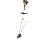
BC210
2-Cycle Gasoline
Trimmer /
Brushcutter
Operator’s Manual