Cub Cadet BC 210 BC 210 Operator's Manual - Page 1
Cub Cadet BC 210 Manual
 |
View all Cub Cadet BC 210 manuals
Add to My Manuals
Save this manual to your list of manuals |
Page 1 highlights
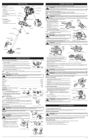
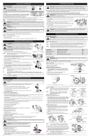
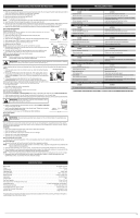
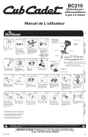
BC210 2-Cycle Gasoline Trimmer / Brushcutter Operator's Manual English - Page 1 Français - Page 6 Removing Unit From Carton 1 Remove all contents from carton. Assemble The Unit (4) Screws 40:1 2 Remove cap from lower boom. Push cutting attachment into coupler. Turn coupler knob clockwise to tighten. Min. 6" Bottom Clamp 3 Place the D-handle over the shaft housing and onto the bottom clamp. Place it a minimum of 6 inches from the end of the shaft grip. 1 Gallon 3.2 oz 4 Mix thoroughly in separate fuel can: - 3.2 fl. oz. of 2-cycle engine oil - 1 gallon of unleaded gasoline NOTE: Do not mix directly in fuel tank. Tools Required • Flat blade screwdriver • T-25 Tox screwdriver • Locking Rod • 13 mm closed-end or socket wrench On/ Off Switch D-Handle Rapid-link™ Starter Rope Fuel Cap Throttle Control Assemble The Unit Starting The Unit Primer Bulb Choke Lever 5 Place unit on a level surface. Fill fuel tank. 10 X 6 Press primer bulb 10 times, or until fuel is visible 7 Move choke lever to Position 1. Starting The Unit Choke Lever 9 SQUEEZE and HOLD throttle for ALL further steps. 5 X 10 Pull rope 5 times. Reloading The Line 11 Move choke lever to Position 2 and squeeze throttle. 18 Crouch in starting position. Cutting Head Shield Line Cutting Blade Cutting Head Blade Shield / Shield Mount Brush Blade Need Help? Call 1-877-282-8684 DIDN'T START? Repeat these instructions. IF engine fails to start after 2 attempts, move choke lever to position 3 and pull the starter rope until engine starts IF unit still fails to start, refer to the operator's manual for additional starting and troubleshooting information Reloading The Line* Choke Lever 3-5 X 12 Pull rope 3-5 times to start engine. Run unit for 30-60 seconds to warm up. 13 Continue to squeeze throttle. Move choke lever to Position 3. 14 Continue to squeeze throttle. Run unit for an additional 60 seconds to complete warm-up. Unit may be used during this time. Spring Spool Inner Reel 1 Bump Knob Unscrew bump knob clockwise. Remove inner reel and spring. 3"-4" 2 Insert 10' of 0.105"SplitLine® through hole in top of reel. Pull most of line through hole until 3"-4" remains. 3 Bend short end and push it into the other hole. Pull tight. 4 Wind line tightly in direction of arrow. Split other end of SplitLine® back 6"-7". For replacement line, call 1-877-282-8684 or go to an authorized service dealer. For single line installation or replacement spool installation instructions, refer to the Replacing the Trimming Line section of this manual. *This is to assist in the reloading of Splitline® only. These instructions are NOT part of the fast assembly instructions. Line does not need to be installed on the initial assembly and start-up. 5 Push 6"-7" ends into the holding slots. 6 Insert lines through eyelets in spool. Insert spring and reel into spool. 7 Hold the inner reel in place. Tighten Bump Knob counterclockwise. 18 Pull lines firmly to release from holding slots. Español - Page 11 IMPORTANT: READ OPERATOR'S MANUAL THOROUGHLY AND FOLLOW THE SAFE OPERATION PRACTICES BEFORE OPERATING THE UNIT. NEED HELP? CALL 1-877-282-8684 IN U.S. OR 1-800-668-1238 IN CANADA 769-07384 P00 12/11
-
 1
1 -
 2
2 -
 3
3 -
 4
4 -
 5
5 -
 6
6 -
 7
7 -
8
-
9
-
10
-
11
-
12
-
13
-
14
-
15
-
16
 |
 |