Cub Cadet BC 210 BC 210 Operator's Manual - Page 3

Know Your Unit, Assembly Instructions, Oil And Fuel Information - operators manual

Page 3 highlights

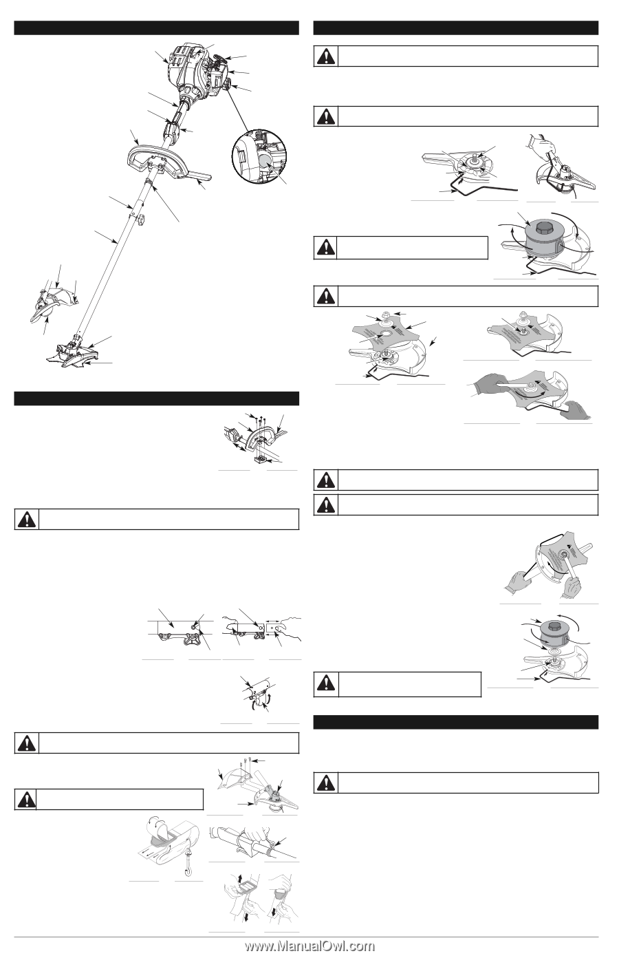
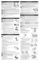
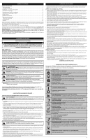
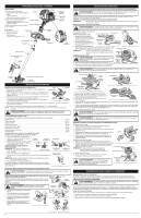
KNOW YOUR UNIT APPLICATIONS As a trimmer: Muffler • Cutting grass and light weeds. • Edging • Decorative trimming around trees, fences, etc. As a brushcutter: • Cut heavy grass and weeds up to 1/2" (1.3 cm) diameter. Shaft Grip Other optional accessories may be used with this unit. On/Off Control Spark Plug Starter Rope Grip Air Filter Cover Fuel Cap Tools Required: • Flat blade screwdriver • T-25 Tox screwdriver • Locking Rod • 13 mm closed-end or socket wrench D-Handle Throttle Control Rapid-link™ Barrier Bar Primer Bulb Shaft Housing Shoulder Strap Clip Cutting Head Shield Line Cutting Blade ASSEMBLY INSTRUCTIONS Install the cutting attachment shield when using the unit as a grass trimmer WARNING: To avoid serious personal injury, the cutting attachment shield MUST be in place at all times while operating the unit as a grass trimmer. Install the cutting attachment shield on the shield mount by inserting the three (3) screws into the shield mount. Tighten securely with a flat blade screwdriver (Fig. 5). REMOVE THE CUTTING ATTACHMENT AND INSTALL THE CUTTING BLADE NOTE: To make cutting blade removal and installation easier, place the unit on the ground or on a work bench. Remove the Cutting Attachment Shield WARNING: The gear housing gets hot with use. It can result in injury to the operator. The housing remains hot for a short time even after the unit is turned off. Do not touch the gear housing until it has cooled. See Remove and Install the Cutting Attachment Shield. Remove the Cutting Attachment 1. Align the shaft bushing hole with the Shaft Bushing Hole locking rod slot and insert the locking rod into the shaft bushing hole (Fig. 9). Output Shaft 2. Hold the locking rod in place by Locking Rod Slot grasping it next to the boom of the unit (Fig. 10). 3. While holding the locking rod, Locking Rod remove the cutting attachment by turning it clockwise off of the output Fig. 9 shaft (Fig. 11). Store the cutting attachment for future use. NOTE: The blade retainer under the cutting attachment will be used when installing the cutting blade. Output Shaft Bushing Cutting Attachment Fig. 10 Install the Cutting Blade WARNING: To avoid serious personal injury, always wear gloves while handling or installing the blade. 4. Place the cutting blade on the output shaft bushing (Fig. 12). 5. Make sure that the cutting blade is centered on the pilot step and sitting flat against the output shaft bushing (Fig. 13). Locking Rod Slot Locking Rod Fig. 11 WARNING: If the cutting blade is off-center, the unit will vibrate and the blade may fly off, causing possible serious personal injury. Cutting Head Blade Shield / Shield Mount Blade Retainer Pilot Hole Nut Cutting Blade Shield Mount Pilot Step Brush Blade ASSEMBLY INSTRUCTIONS INSTALL AND ADJUST THE D-HANDLE Screw (4) Barrier Bar 1. Remove the screws and bottom clamp piece that were installed on the Dhandle for shipping. D-Handle 2. Place the D-handle over the shaft housing and onto the bottom clamp (Fig. 1). Place it a minimum of 6 inches (15.24 cm) from the end of the shaft grip. 3. Start the screws with a large Flat-head or T-25 Torx screwdriver. Do not tighten until making the handle adjustment. 4. If it was pre-installed, loosen the screws on the D-handle just enough to move it. 5. While holding the unit in the operating position (Fig. 20), move the D-handle to the location that provides the best grip. Minimum 6 in. (15.24 cm) Fig. 1 Bottom Clamp 6. Tighten the clamp screws evenly until the D-handle is secure. NOTE: Make sure the barrier bar will point toward the operator's body when the unit is held in the operating position. OPERATING THE RAPID-LINK™ SYSTEM WARNING: Before using any attachment, read and understand the manual that came with the attachment. Follow all safety information contained within. The Rapid-link™ system enables the use of these optional Add-Ons. Trimmer AF720 Hedge Trimmer AH720* Brushcutter BC720* Cultivator GC720 Edger LE720* Pole Saw PS720 Straight Shaft Trimmer SS725 Turbo Blower TB720 * Do NOT use this Add-On with an electric powered unit. REMOVING THE ADD-ON Rapid-link™ Coupler Release Button Primary Hole 1. Turn the knob counterclockwise to loosen (Fig. 4). 2. Press and hold the release button (Fig. 2). 3. While firmly holding the upper shaft housing, pull the lower shaft housing straight out of the Rapidlink™ coupler (Fig. 3). INSTALLING THE ADD-ON Guide Recess Fig. 2 NOTE: To make installing or removing the add-on easier, place the unit on the ground or on a work bench. 1. Turn knob counterclockwise to loosen (Fig. 4). Upper Shaft Housing Fig. 3 90˚ Edging Hole (Trimmer Only) Lower Shaft Housing 2. While firmly holding the add-on, push it straight into the Rapid-link ™ coupler (Fig. 3). NOTE: Aligning the release button with the guide recess will help installation (Fig. 2). 3. Turn the knob clockwise to tighten (Fig. 4). For decorative trimming/edging with the line cutting head, lock the release button into the 90° hole (Fig. 4). Knob REMOVE AND INSTALL THE CUTTING ATTACHMENT SHIELD Fig. 4 WARNING: The cutting attachment shield should NOT be installed when operating the unit with a blade. Remove the cutting attachment shield before removing or installing the blade. Remove the cutting attachment shield when using the unit as a brushcutter Remove the cutting attachment shield from the shield mount by removing the three (3) screws with a flat blade screwdriver (Fig. 5). Store parts for future use. INSTALL THE HARNESS Cutting Attachmen t Shield WARNING: Always use the shoulder harness when using the cutting blade to avoid serious personal injury. Shield Mount 1. Push the strap through the center of the buckle. 2. Pull the strap over the cross bar and down through the slot in the buckle (Fig. 6). 3. Put the harness on over head and onto shoulder. Snap it on to the support fitting (Fig. 7). 4. Adjust length to fit the operator's size. Pull tab to lengthen, pull strap to shorten (Fig 8). Screws (3) Gear Housing Fig. 5 Support Fitting Fig. 7 Fig. 6 Output Shaft Bushing Locking Rod Fig. 13 Fig. 12 6. Align the shaft bushing hole with the locking rod slot and insert the locking rod into the bushing hole (Fig. 9). 7. Put the blade retainer and nut on the output shaft. Make sure that the blade is installed correctly. 1/4-1/2 turn Counterclockwise 8. Tighten nut counterclockwise against the blade while holding the locking rod: Fig. 14 • If using a torque wrench and a 13 mm socket tighten to: 325 - 335 in•lb, 27 - 28 ft.•lb, 37 - 38 N•m. • Without a torque wrench, use a 13 mm closed-end or socket wrench, turning the nut until the blade retainer is snug against the shaft bushing. Make sure that the blade is installed correctly, then rotate the nut an additional 1/4 to 1/2 turn counterclockwise (Fig. 14). 9. Remove the locking rod from the locking rod slot. WARNING: To avoid serious personal injury or damage to the unit, do not start or operate this unit with the locking rod in the locking rod slot. WARNING: Do not sharpen the cutting blade. Sharpening the blade can cause the blade tip to break off while in use. This can result in severe personal injury. Replace the blade. REMOVE THE CUTTING BLADE AND INSTALL THE CUTTING ATTACHMENT Remove the Cutting Blade 1. Align the shaft bushing hole with the locking rod slot and insert the locking rod into the bushing hole (Fig. 9). 2. Hold the locking rod in place by grasping it next to the boom of the unit (Fig.10). clockwise 3. While holding the locking rod, loosen the nut on the blade by turning it clockwise with a 13 mm closed-end or socket wrench (Fig. 15). 4. Remove the nut, blade retainer and blade. Store the nut and blade together for future use in a secure place. Store out of children's reach. Install the Cutting Attachment 5. Align the shaft bushing hole with the locking rod slot and insert the locking rod into the shaft bushing hole (Fig. 9). Place the blade retainer on the output shaft with the flat surface against the output shaft bushing (Fig. 16). Screw the cutting attachment counterclockwise onto the output shaft. Tighten securely. Cutting Attachment NOTE: The blade retainer must be installed on the output shaft in the position shown for the cutting attachment to work correctly. Blade Retainer 6. Remove the locking rod. 7. Install the cutting attachment shield. Refer to Remove and Install the Cutting Attachment Shield. Output Shaft Bushing WARNING: To avoid serious personal injury, the cutting attachment shield MUST be in place at all times while operating the unit as a trimmer. Locking Rod Fig. 15 Fig. 16 OIL AND FUEL INFORMATION OIL AND FUEL MIXING INSTRUCTIONS Old and/or improperly mixed fuel are the main reasons for the unit not running properly. Be sure to use fresh, clean unleaded fuel. Follow the instructions carefully for the proper fuel/oil mixture. DEFINITION OF BLENDED FUELS WARNING: It has been proven that fuel containing greater than 10% ethanol will likely damage this engine and void the warranty. Today's fuels are often a blend of gasoline and oxygenates such as ethanol, methanol, or MTBE (ether). Alcoholblended fuel absorbs water. As little as 1% water in the fuel can make fuel and oil separate. It forms acids when stored. When using alcohol-blended fuel, use fresh fuel (less than 30 days old). USING BLENDED FUELS If choosing to use a blended fuel, or its use is unavoidable, follow recommended precautions: • Always use the fresh fuel mix explained in the operator's manual • Always agitate the fuel mix before fueling the unit • Drain the tank and run the engine dry before storing the unit Fig. 8 3

  • 1
  • 2
  • 3
  • 4
  • 5
  • 6
  • 7
  • 8
  • 9
  • 10
  • 11
  • 12
  • 13
  • 14
  • 15
  • 16

Install the cutting attachment shield when using the unit as a grass trimmer
Install the cutting attachment shield on the shield mount by inserting the three (3) screws into the shield mount. Tighten
securely with a flat blade screwdriver (Fig. 5).
REMOVE THE CUTTING ATTACHMENT AND INSTALL THE CUTTING BLADE
NOTE:
To make cutting blade removal and installation easier, place the unit on the ground or on a work bench.
Remove the Cutting Attachment Shield
See Remove and Install the Cutting Attachment Shield.
Remove the Cutting Attachment
1.
Align the shaft bushing hole with the
locking rod slot and insert the
locking rod into the shaft bushing
hole (Fig. 9).
2.
Hold the locking rod in place by
grasping it next to the boom of the
unit (Fig. 10).
3.
While holding the locking rod,
remove the cutting attachment by
turning it clockwise off of the output
shaft (Fig. 11). Store the cutting attachment for future use.
NOTE:
The blade retainer under the cutting attachment will be used
when installing the cutting blade.
Install the Cutting Blade
4.
Place the cutting blade on the output shaft bushing (Fig. 12).
5.
Make sure that the cutting blade is centered on the pilot step and
sitting flat against the output shaft bushing (Fig. 13).
6.
Align the shaft bushing hole with the locking rod slot and
insert the locking rod into the bushing hole (Fig. 9).
7.
Put the blade retainer and nut on the output shaft. Make
sure that the blade is installed correctly.
8.
Tighten nut counterclockwise against the blade while
holding the locking rod:
If using a torque wrench and a 13 mm socket tighten to: 325 - 335 in•lb, 27 - 28 ft.•lb, 37 - 38 N•m.
Without a torque wrench, use a 13 mm closed-end or socket wrench, turning the nut until the blade retainer is snug
against the
shaft bushing. Make sure that the blade is installed correctly, then rotate the nut an additional 1/4 to 1/2
turn
counterclockwise
(Fig. 14).
9.
Remove the locking rod from the locking rod slot.
Throttle Control
D-Handle
Shaft Grip
Air Filter Cover
Spark Plug
Shaft Housing
Starter Rope Grip
Brush Blade
Muffler
On/Off Control
Blade Shield /
Shield Mount
Fuel Cap
Primer Bulb
Rapid-link™
Barrier Bar
Shoulder
Strap Clip
Line Cutting
Blade
Cutting Head
Cutting Head Shield
Fig. 13
Pilot Step
REMOVE AND INSTALL THE CUTTING ATTACHMENT SHIELD
Remove the cutting attachment shield when using the unit as a
brushcutter
Remove the cutting attachment shield from the shield mount by removing the
three (3) screws with a flat blade screwdriver (Fig. 5). Store parts for future use.
INSTALL THE HARNESS
1.
Push the strap through the center of the
buckle.
2.
Pull the strap over the cross bar and down
through the slot in the buckle (Fig. 6).
3.
Put the harness on over head and onto
shoulder. Snap it on to the support fitting
(Fig. 7).
4.
Adjust length to fit the operator’s size. Pull
tab to lengthen, pull strap to shorten (Fig 8).
3
KNOW YOUR UNIT
INSTALL AND ADJUST THE D-HANDLE
1.
Remove the screws and bottom clamp piece that were installed on the D-
handle for shipping.
2.
Place the D-handle over the shaft housing and onto the bottom clamp (Fig. 1).
Place it a minimum of 6 inches (15.24 cm) from the end of the shaft grip.
3.
Start the screws with a large Flat-head or T-25 Torx screwdriver. Do not tighten
until making the handle adjustment.
4.
If it was pre-installed, loosen the screws on the D-handle just enough to move it.
5.
While holding the unit in the operating position (Fig. 20), move the D-handle to
the location that provides the best grip.
6.
Tighten the clamp screws evenly until the D-handle is secure.
NOTE:
Make sure the barrier bar will point toward the operator’s body when the unit is held in the operating
position.
OPERATING THE RAPID-LINK™ SYSTEM
The Rapid-link™ system enables the use of these optional Add-Ons.
Trimmer. . . . . . . . . . . . . . . . . . . . . . . . . . . . . . . . . . . . . . . . . . . . . . . . . . . . . . . . . . . . . . . . . . . . . . . . . . . . . . . . . . . AF720
Hedge Trimmer*. . . . . . . . . . . . . . . . . . . . . . . . . . . . . . . . . . . . . . . . . . . . . . . . . . . . . . . . . . . . . . . . . . . . . . . . . . . AH720*
Brushcutter* . . . . . . . . . . . . . . . . . . . . . . . . . . . . . . . . . . . . . . . . . . . . . . . . . . . . . . . . . . . . . . . . . . . . . . . . . . . . . . BC720*
Cultivator
. . . . . . . . . . . . . . . . . . . . . . . . . . . . . . . . . . . . . . . . . . . . . . . . . . . . . . . . . . . . . . . . . . . . . . . . . . . . . . . . GC720
Edger*. . . . . . . . . . . . . . . . . . . . . . . . . . . . . . . . . . . . . . . . . . . . . . . . . . . . . . . . . . . . . . . . . . . . . . . . . . . . . . . . . . . LE720*
Pole Saw . . . . . . . . . . . . . . . . . . . . . . . . . . . . . . . . . . . . . . . . . . . . . . . . . . . . . . . . . . . . . . . . . . . . . . . . . . . . . . . . . PS720
Straight Shaft Trimmer
. . . . . . . . . . . . . . . . . . . . . . . . . . . . . . . . . . . . . . . . . . . . . . . . . . . . . . . . . . . . . . . . . . . . . . SS725
Turbo Blower. . . . . . . . . . . . . . . . . . . . . . . . . . . . . . . . . . . . . . . . . . . . . . . . . . . . . . . . . . . . . . . . . . . . . . . . . . . . . . TB720
* Do NOT use this Add-On with an electric
powered unit.
REMOVING THE ADD-ON
1.
Turn the knob
counterclockwise
to loosen (Fig. 4).
2.
Press and hold the release button (Fig. 2).
3.
While firmly holding the upper shaft housing, pull
the lower shaft housing straight out of the Rapid-
link™ coupler (Fig. 3).
INSTALLING THE ADD-ON
NOTE:
To make installing or removing the add-on easier, place the unit on the
ground or on a work bench.
1.
Turn knob
counterclockwise
to loosen (Fig. 4).
2.
While firmly holding the add-on, push it straight into the Rapid-link ™ coupler (Fig. 3).
NOTE:
Aligning the release button with the guide recess will help installation (Fig. 2).
3.
Turn the knob
clockwise
to tighten (Fig. 4).
For decorative trimming/edging with the line cutting head, lock the release button into
the 90° hole
(Fig. 4).
ASSEMBLY INSTRUCTIONS
WARNING:
Before using any attachment, read and understand the manual that came with the
attachment. Follow all safety information contained within.
Guide Recess
Fig. 2
Release
Button
Rapid-link™ Coupler
Upper Shaft
Housing
Fig. 3
Lower Shaft
Housing
Primary Hole
Knob
Fig. 4
90˚ Edging Hole
(Trimmer Only)
D-Handle
Minimum 6 in.
(15.24 cm)
Bottom
Clamp
Screw (4)
Barrier Bar
Fig. 1
WARNING:
The cutting attachment shield should NOT be installed when operating the unit with a
blade. Remove the cutting attachment shield before removing or installing the blade.
WARNING:
Always use the shoulder harness when using the
cutting blade to avoid serious personal injury.
Cutting
Attachmen
t Shield
Shield
Mount
Screws (3)
Gear Housing
Fig. 5
Fig. 6
Support
Fitting
Fig. 7
Fig. 8
ASSEMBLY INSTRUCTIONS
WARNING:
To avoid serious personal injury, the cutting attachment shield MUST be in place at all
times while operating the unit as a grass trimmer.
WARNING:
The gear housing gets hot with use. It can result in injury to the operator. The housing
remains hot for a short time even after the unit is turned off. Do not touch the gear housing until it has
cooled.
Locking Rod Slot
Output Shaft
Bushing
Shaft Bushing Hole
Output Shaft
Fig. 9
Locking Rod
Locking Rod
Slot
Cutting Attachment
Fig. 11
Locking Rod
Fig. 10
WARNING:
To avoid serious personal injury, always wear
gloves while handling or installing the blade.
WARNING:
If the cutting blade is off-center, the unit will vibrate and the blade may fly off, causing
possible serious personal injury.
Shield
Mount
Locking Rod
Cutting
Blade
Blade Retainer
Nut
Output Shaft
Bushing
Pilot Hole
Fig. 12
1/4-1/2 turn
Counterclockwise
Fig. 14
WARNING:
To avoid serious personal injury or damage to the unit, do not start or operate this unit
with the locking rod in the locking rod slot.
WARNING:
Do not sharpen the cutting blade. Sharpening the blade can cause the blade tip to break
off while in use. This can result in severe personal injury. Replace the blade.
REMOVE THE CUTTING BLADE AND INSTALL THE CUTTING ATTACHMENT
Remove the Cutting Blade
1.
Align the shaft bushing hole with the locking rod slot and insert the
locking rod into the bushing hole (Fig. 9).
2.
Hold the locking rod in place by grasping it next to the boom of the
unit (Fig.10).
3.
While holding the locking rod, loosen the nut on the blade by turning it
clockwise
with a 13 mm closed-end or socket wrench (Fig. 15).
4.
Remove the nut, blade retainer and blade. Store the nut and blade
together for future use in a secure place. Store out of children’s reach.
Install the Cutting Attachment
5.
Align the shaft bushing hole with the locking rod slot and insert the
locking rod into the shaft bushing hole (Fig. 9). Place the blade
retainer on the output shaft with the flat surface against the output
shaft bushing (Fig. 16). Screw the cutting attachment
counterclockwise
onto the output shaft. Tighten securely.
NOTE:
The blade retainer must be installed on the output shaft in
the position shown for the cutting attachment to work
correctly.
6.
Remove the locking rod.
7.
Install the cutting attachment shield. Refer to
Remove and Install the
Cutting Attachment Shield
.
clockwise
Fig. 15
Cutting Attachment
Locking Rod
Blade Retainer
Output Shaft
Bushing
Fig. 16
WARNING:
To avoid serious personal injury, the
cutting attachment shield MUST be in place at all times
while operating the unit as a trimmer.
OIL AND FUEL MIXING INSTRUCTIONS
Old and/or improperly mixed fuel are the main reasons for the unit not running properly. Be sure to use fresh, clean
unleaded fuel. Follow the instructions carefully for the proper fuel/oil mixture.
DEFINITION OF BLENDED FUELS
Today's fuels are often a blend of gasoline and oxygenates such as ethanol, methanol, or MTBE (ether). Alcohol-
blended fuel absorbs water. As little as 1% water in the fuel can make fuel and oil separate. It forms acids when
stored. When using alcohol-blended fuel, use fresh fuel (less than 30 days old).
USING BLENDED FUELS
If choosing to use a blended fuel, or its use is unavoidable, follow recommended precautions:
Always use the fresh fuel mix explained in the operator's manual
Always agitate the fuel mix before fueling the unit
Drain the tank and run the engine dry before storing the unit
OIL AND FUEL INFORMATION
WARNING:
It has been proven that fuel containing greater than 10% ethanol will likely damage this engine
and void the warranty.
APPLICATIONS
As a trimmer:
Cutting grass and light weeds.
Edging
Decorative trimming around trees,
fences, etc.
As a brushcutter:
Cut heavy grass and weeds up to 1/2”
(1.3 cm) diameter.
Other optional accessories may be used
with this unit.
Tools Required:
Flat blade screwdriver
T-25 Tox screwdriver
Locking Rod
13 mm closed-end or socket wrench