Cub Cadet BC 210 BC 210 Operator's Manual - Page 4
Maintenance And Repair Instructions, Operating Instructions, Starting/stopping Instructions, Oil - trimmer
 |
View all Cub Cadet BC 210 manuals
Add to My Manuals
Save this manual to your list of manuals |
Page 4 highlights
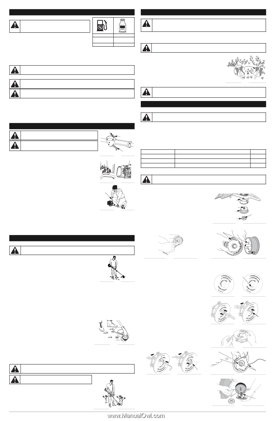
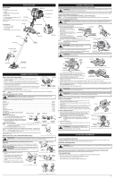
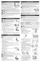
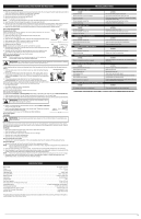
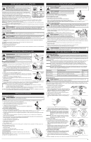
OIL AND FUEL INFORMATION USING FUEL ADDITIVES CAUTION: For proper engine operation and maximum reliability, pay strict attention to the oil and fuel mixing instructions on the 2-cycle oil container. Using improperly mixed fuel can severely damage the engine. The bottle of 2-cycle oil contains a fuel additive which will help inhibit corrosion and minimize the formation of gum deposits. It is recommended to use our 2-cycle oil UNLEADED GAS with this unit. 1 GALLON US If unavailable, use a good 2-cycle oil designed for air-cooled engines along with (3.8 LITERS) a fuel additive, such as STA-BIL® Gas Stabilizer or an equivalent. Add 0.8 oz. 1 LITER 2 CYCLE OIL 3.2 FL. OZ. (95 ml) 25 ml (23 ml) of fuel additive per gallon of fuel according to the instructions on the container. NEVER add fuel additives directly to the unit's fuel tank. MIXING RATIO - 40:1 Thoroughly mix the proper ratio of 2-cycle engine oil with unleaded fuel in a separate fuel can. Use a 40:1 fuel/oil ratio. Do not mix them directly in the engine fuel tank. See the table for specific gas and oil mixing ratios. NOTE: One gallon (3.8 liters) of unleaded fuel mixed with one 3.2 oz. (95 ml) bottle of 2-cycle oil makes a 40:1 fuel/oil ratio. NOTE: Dispose of the old fuel/oil mix in accordance to Federal, State and Local regulations. WARNING: Gasoline is extremely flammable. Ignited vapors may explode. Always stop the engine and allow it to cool before filling the fuel tank. Do not smoke while filling the tank. Keep sparks and open flames at a distance from the area. FUELING THE UNIT WARNING: Remove fuel cap slowly to avoid injury from fuel spray. Never operate the unit without the fuel cap securely in place. WARNING: Add fuel in a clean, level and well ventilated outdoor area. Wipe up any spilled fuel immediately. Avoid creating a source of ignition for spilled fuel. Do not start the engine until fuel vapors dissipate. 1. Turn unit on its side, with the fuel cap facing up, and remove the fuel cap. 2. Place the gas container's spout into the fill hole on the fuel tank and fill the tank. NOTE: Do not overfill the tank. 3. Wipe up any gasoline that may have spilled. 4. Reinstall the fuel cap. 5. Move the unit at least 30 ft. (9.1 m) from the fueling source and site before starting the engine. STARTING/STOPPING INSTRUCTIONS WARNING: Operate this unit in a well-ventilated outdoor area. Carbon monoxide exhaust fumes can be lethal in a confined area. OFF (O) ON (I) WARNING: Avoid accidental starting. Make sure you are in the starting position when pulling the starter rope (Fig. 19). To avoid serious injury, the operator and unit must be in a stable position while starting. STARTING INSTRUCTIONS Throttle Control 1. Mix fuel with oil. See Oil and Fuel Mixing Instructions. Fig. 17 2. Fill the fuel tank with fresh, clean fuel mix. Refer to Fueling the Unit. Choke Lever Primer Bulb NOTE: There is no need to turn the unit on. The On/Off Control is in the ON ( I ) position at all times (Fig. 17). 3. Fully press and release the primer bulb 10 times, slowly. Some amount of fuel should be visible in the primer bulb and fuel lines (Fig. 18). If fuel can not be seen in the bulb, press and release the bulb until fuel is visible. 4. Place the choke lever in Position 1 (Fig. 18). 5. Crouch in the starting position (Fig. 19). Squeeze the throttle control lever. Pull the starter rope 5 times. Fig. 18 6. Place the choke lever in Position 2 (Fig. 18) 7. Squeeze the throttle control, pull the starter rope in a controlled motion 3 to 5 times to start engine. Starter Rope Starting Position 8. Keep the throttle squeezed and allow the engine to warm up for 30 to 60 seconds. 9. Continue squeezing the throttle control, move the choke lever to Position 3 (Fig. 18) and continue warming the engine for an additional 60 seconds. The unit may be used during this time. NOTE: IF... Unit is properly warmed up when engine accelerates without hesitation. the engine hesitates, return the choke lever to Position 2 (Fig. 18) and continue warm-up. Fig. 19 IF... the engine does not start, go back to step 3. IF... the engine fails to start after 2 attempts, place the choke lever in Position 3 and squeeze the throttle control. Pull the starter rope out with a controlled and steady motion 3 to 8 times. The engine should start. If not, repeat. IF WARM... If the engine is already warm, start the unit with the choke lever in Position 2. After the unit starts, move the choke lever to Position 3. OPERATING INSTRUCTIONS HOLDING THE TRIMMER WARNING: Always wear eye, hearing, foot and body protection to reduce the risk of injury when operating this unit. Before operating the unit, stand in the operating position (Fig. 20). Check for the following: • The operator is wearing eye protection and proper clothing • With a slightly-bent right arm, the operator's hand is holding the shaft grip • The operator's left arm is straight, the left hand holding the D-handle • The unit is at waist level • The cutting head is parallel to the ground and easily contacts the grass without the need to bend over TIPS FOR BEST TRIMMING RESULTS Fig. 20 • Keep the cutting head parallel to the ground. • Do not force the cutting head. Allow the tip of the line to do the cutting, especially along walls. Cutting with more than the tip will reduce cutting efficiency and may overload the engine. • Cut grass over 8 inches (200 mm) by working from top to bottom in small increments to avoid premature line wear or engine drag. • Cut from right to left whenever possible. Cutting to the left improves the unit's cutting efficiency. Clippings are thrown away from the operator. • Slowly move the unit into and out of the cutting area at the desired height. Move either in a forward-backward or side-to-side motion. Cutting shorter lengths produces the best results. • Trim only when grass and weeds are dry. • The life of the cutting line is dependent upon: • Following the trimming techniques • What vegetation is being cut • Where vegetation is cut For example, the line will wear faster when trimming against a foundation wall as opposed to trimming around a tree. Some line breakage will occur from: • Entanglement with foreign matter • Normal line fatigue • Attempting to cut thick, stalky weeds Fig. 21 • Forcing the line into objects such as walls or fence posts DECORATIVE TRIMMING Decorative trimming is accomplished by removing all vegetation around trees, posts, fences, etc. Rotate the whole unit so that the cutting head is at a 30° angle to the ground (Fig. 21). USING THE CUTTING BLADE WARNING: Always wear eye, hearing, foot, body protection and the shoulder strap to reduce the risk of injury when operating this unit. WARNING: Do not use the cutting blade for edging or as an edger. Severe personal injury to yourself or others can result. Before operating the unit with the cutting blade, stand in the operating position (Fig. 22). Refer to Holding the Trimmer. Cutting Blade Operating Tips To establish a rhythmic cutting procedure: • Plant feet firmly, comfortably apart. • Bring the engine to full throttle before entering the material to be cut. At full throttle the blade has maximum cutting power and is less likely to bind, stall or cause blade thrust (which can result in serious personal injury to the operator or others). 4 Fig. 22 OPERATING INSTRUCTIONS WARNING: Blade thrust may occur when the spinning blade contacts an object that it does not immediately cut. Blade thrust can be violent enough to cause the unit and/or operator to be propelled in any direction, and possibly lose control of the unit. Blade thrust can occur without warning if the blade snags, stalls or binds. This is more likely to occur in areas where it is difficult to see the material being cut. • Cut while swinging the upper part of your body from left to right. • Always release the throttle trigger and allow the engine to return to idle speed when not cutting. • When you are finished, always unsnap the unit from the harness before taking off the harness. WARNING: The blade continues to spin after the engine is turned off. The coasting blade can seriously cut you if accidentally touched. • Swing the unit in the opposite direction as the blade spins, which increases the cutting action. • After the return swing, move forward to the next area to be cut and plant your feet again. • The cutting blade is designed with a second cutting edge. You can use it by removing the blade, turning it upside down and reinstalling it. To reduce the chance of material wrapping around the blade, follow these steps: • Cut at full throttle. • Swing the unit into material to be cut from your left to your right (Fig. 23). • Avoid the material just cut as you make the return swing. Fig. 23 WARNING: Do not clear away any cut material with the engine running or blade turning. To avoid serious personal injury, turn off the engine. Allow the blade to stop before removing materials wrapped around the blade shaft. MAINTENANCE AND REPAIR INSTRUCTIONS MAINTENANCE SCHEDULE WARNING: To prevent serious injury, never perform maintenance or repairs with unit running. Always service and repair a cool unit. Disconnect the spark plug wire to ensure that the unit cannot start. Perform these required maintenance procedures at the frequency stated in the table. These procedures should also be a part of any seasonal tune-up. NOTE: Some maintenance procedures may require special tools or skills. If you are unsure about these procedures take your unit to any non-road engine repair establishment, individual or authorized service dealer. NOTE: Maintenance, replacement, or repair of the emission control devices and system may be performed by any non-road engine repair establishment, individual or authorized service dealer. NOTE: Please read the California/EPA statement that came with the unit for a complete listing of terms and coverage for the emissions control devices, such as the spark arrestor, muffler, carburetor, etc. FREQUENCY MAINTENANCE REQUIRED SEE Before starting engine Fill fuel tank with fresh fuel p. 3 Every 10 hours Clean and re-oil air filter p. 5 Every 25 hours Check spark plug condition and gap p. 5 LINE INSTALLATION WARNING: Never use metal-reinforced line, wire, chain or rope. These can break off and become dangerous projectiles. This section covers both SplitLine™ and standard single line installation. Always use original equipment manufacturer 0.105 in. (2.67 mm) replacement line. Other types of line may make the engine overheat or fail. There are two methods to replace the trimming line: • Wind the inner reel with new line • Install a prewound inner reel Outer Spool WINDING THE EXISTING INNER REEL 1. Hold the outer spool with one hand and unscrew the Bump Knob clockwise (Fig. 24). Inspect the bolt inside the bump knob to make sure it moves freely. Replace the bump knob if damaged. 2. Remove the inner reel from the outer spool (Fig. 24). Spring Inner Reel Bolt Bump Knob 3. Remove spring from the inner reel (Fig. 24). Fig. 24 4. Use a clean cloth to clean the inner reel, spring, shaft and inner surface of the outer spool (Fig. 25). Indexing Teeth Fig. 25 Fig. 26 5. Check the indexing teeth on the inner reel and outer spool for wear (Fig. 26). If necessary, remove burrs or replace the reel and spool. NOTE: SplitLine™ can only be used with the inner reel with the slotted holes. Single line can be used on either type of inner reel. Use Figure 27 to identify the inner reel you have. For Use with Single Line ONLY For Use with SplitLine™ or Single Line Slotted Holes NOTE: Always use the correct line length when installing trimming line on the unit. The line may not release properly if the line is too long. SINGLE LINE INSTALLATION Go To Step 8 for SplitLine™ Installation 6. Take approximately 18 feet (6 m) of new trimming line, loop it into two equal lengths. Insert each end of the line through one of the two holes in the inner reel (Fig. 28). Pull the line through the inner reel so that the loop is as small as possible. Fig. 27 7. Wind the lines in tight even layers, onto the reel (Fig. 29). Wind the line in the direction indicated on the inner reel. Place your index finger between the two lines to stop the lines from over- lapping. Do not overlap the ends of the line. Proceed to step 11. Loop SPLITLINE™ INSTALLATION 8. Take approximately 9 feet (3 m) of new trimming line. Insert one end of the line through one of the two holes in the inner reel (Fig. 30). Pull the line through the inner reel until only about 4 inches is left out. Fig. 28 9. Insert the end of the line into the open hole in the inner reel and pull the line tight to make the loop as small as possible (Fig. 30). 10. Before winding, split the line back about 6 inches. 11. Wind the line in tight even layers in the direction indicated on the inner reel. Fig. 29 Loop Fig. 30 NOTE: Failure to wind the line in the direction indicated will cause the cutting attachment to operate incorrectly. 12. Insert the ends of the line into the two holding slots (Fig. 31). 13. Insert the ends of the line through the eyelets in the outer spool and place inner reel with spring inside the outer spool (Fig. 32). Push the inner reel and outer spool together. While holding the inner reel and outer spool, grasp the ends and pull firmly to release the line from the holding slots in the reel. NOTE: The spring must be assembled on the inner reel before reassembling the cutting attachment. 14. Hold the inner reel in place and install the bump knob by turning counterclockwise. Tighten securely. Fig. 31 Holding Slots Fig. 32 Spring
-
 1
1 -
 2
2 -
 3
3 -
 4
4 -
 5
5 -
 6
6 -
 7
7 -
 8
8 -
 9
9 -
 10
10 -
11
-
12
-
13
-
14
-
15
-
16
 |
 |