Cub Cadet CC 30 e Electric Rider Operation Manual - Page 14
Service
 |
View all Cub Cadet CC 30 e Electric Rider manuals
Add to My Manuals
Save this manual to your list of manuals |
Page 14 highlights
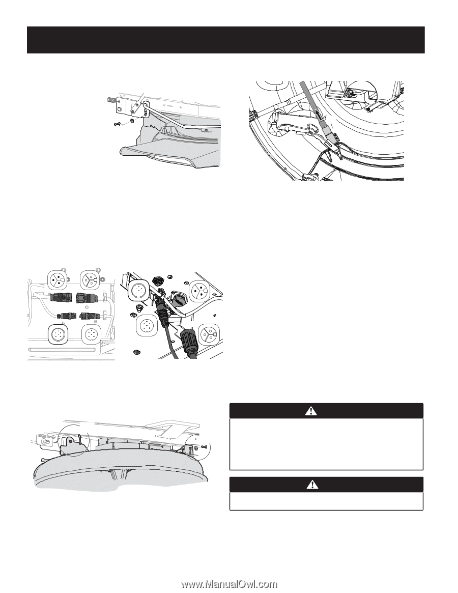
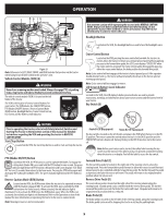
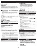
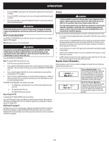
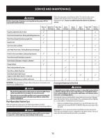
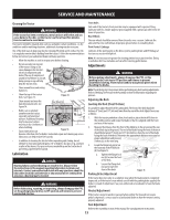
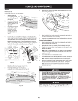
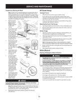
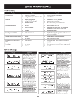
SERVICE AND MAINTENANCE Service Deck Removal To remove the cutting deck, proceed as follows: 1. Power off the tractor, remove the key from the key switch, and engage the parking brake. 2. Lower the deck by moving (b) the deck lift lever into the (a) lowest (#1) position on the right fender. 3. Remove the bow-tie cotter pin (a) and flat washer (b) from the deck lift assembly, and retain for reinstallation later. See Figure 16. Figure 16 6. Unplug the wire connector (a) from the safety switch (b) at the rear of the chute opening. See Figure 20. (a) (b) Figure 20 7. Move the deck lift lever into the highest (#5) position on the right fender to 4. Disconnect the deck motor(s) from the adapters on the underside of the raise the deck lift arms up and out of the way. tractor. Rotate the collar on the larger connector (a) counterclockwise and carefully pull apart. Repeat the procedure with the smaller connector (b). Note: Your mower may have one of two different deck motor connector setups. If your mower has horizontally positioned connectors, see Figure 17. If your mower has vertically positioned connectors, see Figure 18. 8. Gently slide the cutting deck (from the left side) out from underneath the tractor. Cutting Deck Installation 1. Raise the deck lift lever into the highest (#5) position on the right fender to move the deck lift arms out of the way. 2. Gently slide the cutting deck (from the left side) back under the tractor. 3. Plug the wire connector (a) into the safety switch (b) at the rear of the chute (a) opening. See Figure 20. Note: Be sure to securely reconnect the wire connector to the safety switch (b) in Figure 20, you tractor will not start or operate without the safety switch properly connected. (b) (a) 4. Lower the deck lift lever to the lowest (#1) position. 5. Secure the deck to the deck lift arms using two bow-tie cotter pins. See Figure 19. Note: The bow-tie cotter pins (a) should be installed from the top down. Figure 17 Figure 18 Note: Always disconnect the larger connector first. 5. Remove the remaining bow-tie cotter pins (a) securing the deck to the tractor, as shown in Figure 19. 6. Reconnect the deck motors on the underside of the tractor. Always connect the larger connector first and then the smaller connector. See Figure 17. Note: When reconnecting the deck motors, you must be sure that the connections are secure. Blade WARNING (a) • Power off the tractor and remove the key before removing the cutting blade(s) for sharpening or replacement. Protect your (a) hands by using heavy gloves when grasping the blade. • Periodically inspect the blade and/or deck motor casting for cracks or damage, especially after you've struck a foreign object. Do not operate the tractor until damaged components are replaced. Figure 19 CAUTION If the cutting edge of the blade has previously been sharpened, or if any metal separation is present, replace the blade with a new one. 14
-
 1
1 -
2
-
3
-
4
-
5
-
6
-
7
-
8
-
 9
9 -
 10
10 -
 11
11 -
 12
12 -
 13
13 -
 14
14 -
 15
15 -
 16
16 -
 17
17 -
 18
18 -
 19
19 -
20
-
21
-
22
-
23
-
24
-
25
-
26
-
27
-
28
-
29
-
30
-
31
-
32
-
33
-
34
 |
 |