Cub Cadet CC 30 e Electric Rider Operation Manual - Page 7
Assembly
 |
View all Cub Cadet CC 30 e Electric Rider manuals
Add to My Manuals
Save this manual to your list of manuals |
Page 7 highlights
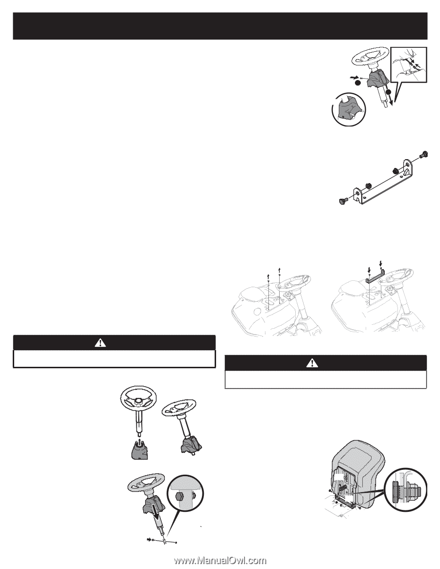
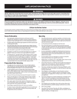
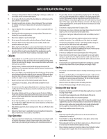
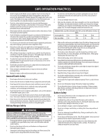
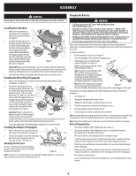
ASSEMBLY Note: All references in this manual to the left or right side and front or back of the tractor are from the operating position only. Exceptions, if any, will be specified. Note: Some components may come already assembled. If they are already assembled, skip ahead to the next step. Preparation Before beginning installation, remove all the contents from the crate and all the hardware from the pack to make sure everything is present. Hardware is listed below. Contents of Crate • Tractor • Steering Pedestal Cap • Discharge Chute Assembly • Hardware Bag • Product Registration Card • Operator's Manual • Mulch Plug • Battery Charger • Steering wheel/ Shaft Assembly • Seat Assembly • Front Bumper • Battery Charger Manual • Hardware Pack: Seat Mounting Bracket (w/ two shoulder bolts & lock nuts installed) Recommended Tools for Assembly • 1/4" or 3/8" drive ratchet • 3/8" wrench and/or socket • 7/16" wrench and/or socket • 1/2" wrench and/or socket • 9/16" wrench and/or socket • Phillips screw driver Manually Moving the Tractor 5. Tighten the shoulder bolt and lock nut using a 9/16" wrench or socket and 7/16" wrench or socket. (a) 6. Remove the pedestal cap mount screw (factory installed) located on the tractor's steering console. Retain the screw for later instructions. See Figure 3. 7. Connect the headlight wire terminals (b) (a). Slide the pedestal cap (b) down onto the tractor and slightly rotate to the right to clip into place. Secure the pedestal cap (b) with the screw (c) previously removed. See Figure 3. (c) 2 (b) 1 Figure 3 Installing Operator's Seat (a) 1. Remove the shoulder bolts (a) and lock nuts (b) from the seat mounting bracket (c) included in your hardware pack. See Figure 4. (b) (b) (a) (c) 2. Remove the two self-tapping bolts (a) factory installed on the tractor. See Figure 5. Figure 4 3. Align the seat bracket (a) in place over the holes from where the self-tapping bolts (b) were removed, as shown in Figure 6. 4. Using a 1/4" drive ratchet with a 3/8" socket, secure the seat bracket (a) with the self-tapping bolts (b) removed in step 2. See Figure 6. (a) (a) (b) (a) (b) CAUTION Figure 5 Figure 6 Never tow your tractor. Towing the tractor with the rear wheels on the ground may cause severe damage to the drive motors. The tractor can be moved as long as the parking brake is not set. The tractor can be pushed slowly. Installing the Steering Wheel Assembly 1. Slide the pedestal cap (a) onto the steering shaft (b) so that when the steering shaft (b) is installed on the tractor, the pedestal cap (a) will be (b) upright as shown in Figure 1. 2. Remove the shoulder bolt (c) and lock nut (d) from the steering shaft and (a) retain for later steps. See Figure 2. 3. Position the steering wheel assembly over the lower steering shaft on the tractor. Align the steering wheel so (a) that its largest opening faces forward when the tractor wheels are straight. (a) (b) Figure 1 (c) (d) 4. Lower the steering wheel assembly (a) onto the lower steering shaft (b) and secure with the shoulder bolt (c) and lock nut (d) previously removed. See Figure 2. (c) (b) (d) CAUTION Do not use any type of power tool (e.g. impact gun or electric drill with nut driver attached) when tightening the self-tapping bolts to attach the seat bracket. 5. Position the seat assembly over the seat mounting bracket, aligning the holes provided. See Figure 7. 6. Install the two shoulder bolts (a) and lock nuts (b) removed from the seat mounting bracket (c) in Step 1. See Figure 7. Note: Make sure that the bolt's shoulder is completely recessed into the seat bracket when securing the lock nut. 7. To adjust the position of the seat, loosen the adjustment knob (d) (d) on the bottom of the seat. Slide the seat forward or backward as desired. Securely retighten the adjustment knob. Refer to D in Figure 7. (a) (b) (c) (b) (a) (b) (a) (c) Figure 7 Figure 2 7
-
 1
1 -
 2
2 -
 3
3 -
 4
4 -
 5
5 -
 6
6 -
 7
7 -
 8
8 -
 9
9 -
 10
10 -
 11
11 -
 12
12 -
13
-
14
-
15
-
16
-
17
-
18
-
19
-
20
-
21
-
22
-
23
-
24
-
25
-
26
-
27
-
28
-
29
-
30
-
31
-
32
-
33
-
34
 |
 |