Cub Cadet Z-Force SX 54 Operation Manual - Page 10
Controls & Operation
 |
View all Cub Cadet Z-Force SX 54 manuals
Add to My Manuals
Save this manual to your list of manuals |
Page 10 highlights
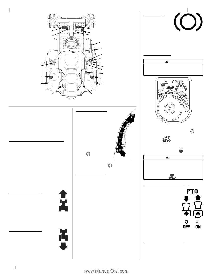
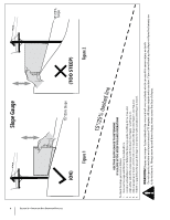
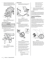
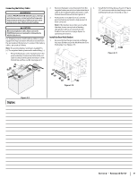
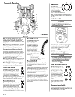
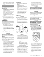
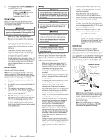
Controls & Operation (F) (R) (K) (J) (L) (M) (B) (C) (A) (E) (D) (N) (O) (Q) (H) (G) (P) † (L) † (M) † 3 Brake Pedal (F) The brake pedal is located on the left front side of the running board. The brake pedal can be used for sudden stops or setting the parking brake. Note: The brake pedal must be fully depressed to activate the safety interlock switch when starting the rider. Ignition Module (G) WARNING Never leave a running machine unattended. Always disengage PTO, set parking brake, stop engine and remove key to prevent unintended starting. (I) (I) † -- If Equipped Figure 3-1 Note: This Operator's Manual covers several models. Tractor features may vary by model. Not all features in this manual are applicable to all tractor models and the tractor depicted may differ from yours. Note: References to LEFT, RIGHT, FRONT, and REAR indicate that position on the tractor when facing forward while seated in the operator's seat. Steering Column Adjustment Lever (A) The steering column adjustment lever is located on the right side of the steering column. To adjust the angle of the steering column rotate the lever counterclockwise, move the steering column to the desired position and then rotate the lever clockwise to lock it into position. Note: Be sure that the steering column adjustment lever is tight to prevent the column from moving when operating the tractor. Deck Height Index (D) The deck height index consists of several holes located on the front of the RH console. Each hole corresponds to a 1⁄4" change in the deck height position ranging from 1" at the lowest notch to 4" at the highest notch. The highest notch is also the transport position and the lowest position is the deck removal/installation position . 4" 3.5 3 2.5 2 1.5 1" Note: Do not cut grass in the deck removal/ installation position . Doing so is detrimental to the belt life. Deck Lift Handle (E) Note: The handle is spring loaded so that it can moved out of the way after tightening. Pull the handle out and rotate it to the desired position. The deck lift handle is located on the front of the RH console, and is used to raise and lower the tractor deck. Forward Drive Pedal (B) The forward drive pedal is located on the right side of the machine, along the running board. Press the forward drive pedal forward to cause the tractor to travel forward. Ground speed is also controlled with the forward drive pedal. The further forward the pedal is pivoted, the faster the tractor will travel. The pedal will return to its original/neutral position when it's not pressed. Reverse Drive Pedal (C) The reverse drive pedal is located on the right side of the tractor along the running board. Ground speed is also controlled with the reverse drive pedal. The further downward the pedal is pivoted, the faster the tractor will travel. The pedal will return to its original/neutral position when it's not pressed. Depress the button on the end of the handle and push downward to lower the deck, or pull upward to raise the deck. When the desired height is attained, secure the pin in the desired index hole and release the button on the handle. Note: Make certain the deck is secured and the pin is fully inserted into the deck height index. The pin is keyed to help keep it in place and fits into the slotted holes on the deck height index. Note: The deck lift handle must always be above the pin, never hang the deck lift handle from the pin when mowing. To start the engine, insert the key into the ignition module and turn clockwise to the START position. Release the key into the NORMAL MOWING MODE has fired. position once the engine To stop the engine, turn the ignition key counterclockwise to the STOP position. CAUTION Prior to operating the tractor, refer to both Safety Interlock Switches and Starting The Engine in the Operation section of this manual for detailed instructions regarding the Ignition Switch Module and operating the tractor in REVERSE CAUTION MODE . Power Take-Off (PTO) Switch (H) The PTO switch is located on the RH console to the left of the hour meter/indicator panel. The PTO switch operates the electric PTO clutch mounted on the bottom of the engine crankshaft. Pull the switch knob upward to engage the PTO clutch, or push the knob downward to disengage the clutch. The PTO switch must be in the "OFF" position when starting the engine. Transmission Bypass Rods (I) The transmission bypass rods (one for each the RH and LH transmission) are located on the rear of the tractor, just inside each rear wheel. 10
-
 1
1 -
2
-
3
-
4
-
 5
5 -
 6
6 -
 7
7 -
 8
8 -
 9
9 -
 10
10 -
 11
11 -
 12
12 -
 13
13 -
 14
14 -
 15
15 -
16
-
17
-
18
-
19
-
20
-
21
-
22
-
23
-
24
-
25
-
26
-
27
-
28
-
29
-
30
-
31
-
32
-
33
-
34
-
35
-
36
-
37
-
38
-
39
-
40
-
41
-
42
-
43
-
44
 |
 |