Cub Cadet Z-Force SX 54 Operation Manual - Page 20
Service
 |
View all Cub Cadet Z-Force SX 54 manuals
Add to My Manuals
Save this manual to your list of manuals |
Page 20 highlights
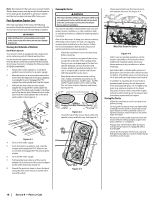
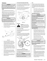
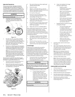
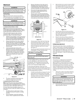
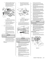
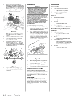
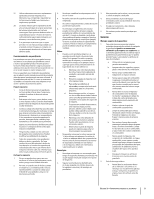
3. Engines stored between 30 and 90 days need to be treated with a gasoline stabilizer and engines stored over 90 days need to be drained of fuel to prevent deterioration and gum from forming in fuel system or on essential carburetor parts. If the gasoline in your engine deteriorates during storage, you may need to have the carburetor, and other fuel system components, serviced or replaced. WARNING Drain fuel only into an approved container outdoors, away from an open flame. Allow engine to cool. Extinguish cigarettes, cigars, pipes, and other sources of ignition prior to draining fuel. 3. Remove the spark plugs and pour approximately one ounce of oil into each cylinder. Crank the engine one or two turns to spread the oil evenly on the cylinder walls. Replace the spark plugs. 4. Clean the engine and the entire tractor thoroughly. Note: Use of a pressure washer or garden hose is not recommended to clean your tractor. They may cause damage to electrical components, spindles, pulleys, bearings or the engine. The use of water will result in shortened life and reduce serviceability. 5. Sharpen the blades so that the tractor will be ready to use when needed. 6. Protect the metal surfaces. Repair scratches with the appropriate touch-up spray paint. Brush a rust preventive oil on any unpainted surfaces including the pulleys and blades. (Be careful not to get any oil on the drive belts.) 7. Clean and fully charge the battery, then disconnect the negative cable at the battery to prevent possible discharge. Recharge the battery periodically when in storage. Note: Remove the battery if exposed to prolonged periods of sub-freezing temperatures. Store in a cool, dry location where temperatures are above freezing. 8. Lubricate all lubrication points. 9. Jack the tractor up and store it on blocks to take the weight off of the tires. Removing the Tractor from Storage 1. Check the engine oil. 2. Fully charge the battery, lower tractor off blocks, and inflate the tires to the recommended pressure. 3. Remove the spark plugs and wipe them off. Using the starter, crank the engine to pump the excess oil out of the spark plug holes. Replace the spark plugs and the ignition leads. 4. If drained before storing, fill the fuel tank with clean, fresh gasoline. 5. Check the level of the engine oil in the crankcase and the hydraulic reservoir tank. 6. Start the engine and allow to idle for a few minutes to ensure engine is operating properly. 7. Drive the tractor without a load to make certain all the tractor systems are functioning properly. Service Battery Removal WARNING Battery posts, terminals and related accessories contain lead and lead compounds. Wash hands after handling. The battery is located beneath the seat frame. To remove the battery: 1. Remove the hex washer screw (a) securing the battery hold-down bracket (b) to the frame. Then flip the battery hold-down bracket (b) up to free the battery. See Figure 4-9. (a) (b) Figure 4-9 2. Remove the hex cap screw and sems nut securing the black negative battery lead to the negative battery post (marked NEG). Move the cable away from the negative battery post. 3. Remove the hex cap screw and sems nut securing the red positive battery lead to the positive battery post (marked POS). 4. Carefully lift the battery out of the tractor. 5. Install the battery by repeating the above steps in the reverse order. WARNING Always connect the positive lead to the battery before connecting the negative lead. This will prevent sparking or possible injury from an electrical short caused by contacting the tractor body with tools being used to connect the cables. Charging the Battery Test and, if necessary, recharge the battery after the tractor has been stored for a period of time. • A voltmeter or load tester should read 12.6 volts (DC) or higher across the battery terminals. See Figure 4-10. Voltmeter Reading 12.7 12.4 12.2 12.0 State of Charge 100% 75% 50% 25% Charging Time Full Charge 90 Min. 180 Min. 280 Min. Figure 4-10 • Charge the battery with a 12-volt battery charger at a MAXIMUM rate of 10 amps. Servicing Electrical System A fuse is installed to protect the tractor's electrical system from damage caused by excessive amperage. Always use the same capacity fuse for replacement. If the electrical system does not function, check for a blown fuse. If you have a recurring problem with blown fuses, have the tractor's electrical system checked by your authorized service dealer. Relays and Switches There are several safety switches in the electrical system. If a function of the safety interlock system described earlier is not functioning properly, have the electrical system checked by your authorized service dealer. Parking Brake Adjustment If the tractor does not come to a complete stop when the control levers are moved fully outward engaging the parking brake, or if the tractor's rear wheels can roll with the parking brake engaged (and the hydrostatic relief valve open), the brake is in need of adjustment. See your authorized service dealer to have the brake adjusted. Deck Removal Remove the tractor deck from the tractor as follows: 1. Move the tractor to a level surface, disengage the PTO, stop the engine place the control levers in the neutral/parking brake engaged position. 2. Move the deck gauge wheels or rollers to their highest setting (lowest deck setting). 3. Remove the 'V' belt from the PTO pulley, located on the bottom of the engine, using one of the following two methods. WARNING The muffler at the rear of the tractor may be extremely hot, and could cause serious burns. Use extreme caution when near the muffler. Allow the muffler to fully cool before removing the belt from the PTO pulley. 4. Releasing belt tension with the idler pulley: a. Using the deck lift handle, raise the deck to the position that provides the most horizontal run of the belt between the deck idler pulleys and the PTO pulley on the bottom of the engine. See Figure 4-11. Transport Position/ Highest Mowing Position Deck Removal/ Installation Position Lowest Mowing Position Figure 4-11 20 Section 4 - Product Care
-
 1
1 -
2
-
3
-
4
-
5
-
6
-
7
-
8
-
9
-
10
-
11
-
12
-
13
-
14
-
 15
15 -
 16
16 -
 17
17 -
 18
18 -
 19
19 -
 20
20 -
 21
21 -
 22
22 -
 23
23 -
 24
24 -
 25
25 -
26
-
27
-
28
-
29
-
30
-
31
-
32
-
33
-
34
-
35
-
36
-
37
-
38
-
39
-
40
-
41
-
42
-
43
-
44
 |
 |