Cub Cadet Z-Force SX 54 Operation Manual - Page 19
Adjustments, Off-Season Storage
 |
View all Cub Cadet Z-Force SX 54 manuals
Add to My Manuals
Save this manual to your list of manuals |
Page 19 highlights
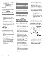
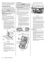
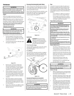
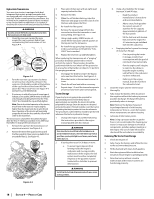
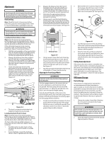
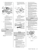
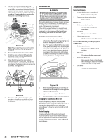
Adjustments WARNING Shut the engine off, remove the ignition key and engage the parking brake before making adjustments. Protect your hands by using heavy gloves when handling the blades. Deck Leveling Note: Check the tractor's tire pressure before performing any deck leveling adjustments. Refer to Tires for information regarding tire pressure. WARNING Shut the engine off, remove the ignition key and engage the parking brake before making adjustments. Protect your hands by using heavy gloves when handling the blades. Leveling the Deck (Side-to-Side) Note: Check the tractor's tire pressure before performing any deck leveling adjustments. Refer to Tires for information regarding tire pressure. Always level the deck side-to-side before front to rear. If the cutting deck appears to be mowing unevenly, a side-to-side adjustment can be performed. Adjust if necessary as follows: 1. With the tractor parked on a firm, level surface, place the deck lift handle in a middle mowing position and rotate both outside blades so that they are perpendicular with the tractor. 2. Measure the distance from the outside of the left blade tip to the ground and the distance from the outside of the right blade tip to the ground. Both measurements taken should be equal. If they're not, proceed to the next step. 3. Loosen the lower jam nut (a) on the adjustable lift link (b) attached to the deck lift arm (c) to lower the deck and tighten the upper jam nut (d) to secure the deck in place, loosen the upper jam nut (d) then tighten the lower jam nut (a) to raise the deck and secure the deck in place. See Figure 4-6. (b) (d) (a) (c) Figure 4-6 4. The deck is properly leveled when both blade tip measurements are equal. Leveling the Deck (Front-To-Rear) Note: Check the tractor's tire pressure before performing any deck leveling adjustments. Refer to Tires for information regarding tire pressure. Always level the deck side-to-side before front to rear. The front of the deck should be between 1⁄4-3⁄8" lower than the rear of the deck. Adjust if necessary as follows: 1. Park the tractor on a firm, level surface and place the deck lift handle in a middle position. 2. Rotate the blade nearest the discharge chute so that it is parallel with the tractor. 3. Measure the distance from the front of the blade tip to the ground and the rear of the blade tip to the ground. The first measurement taken should be between 1⁄4" and 3⁄8" less than the second measurement. 4. Determine the approximate distance necessary for proper adjustment and proceed, if necessary. 5. Using a wrench, raise the front of deck by loosening the lock nuts (a) to the front of the pivot pin (b) and then tighten the jam nuts (c) on the back of the pivot pin to raise the front of the deck and secure in place. See Figure 4-7. (c) (b) (a) Bottom View Figure 4-7 6. Using a wrench, lower the front of deck by loosening the jam nuts (c) on the back of the pivot pin (b) and then tighten the lock nut (a) on the front of the pivot pin to lower the front of the deck and secure in place. See Figure 4-7. 7. The deck is properly leveled when the front tip of the blade is 1⁄4" lower than the rear tip. Adjusting the Front Gauge Wheels WARNING Keep hands and feet away from the discharge opening of the cutting deck. The front gauge wheels on the tractor deck are an anti-scalp feature, and should not ride on the ground. The front gauge wheels should be approximately 1⁄4-1⁄2" above the ground when the deck is set in the desired height setting. Using the deck lift handle, set the deck in the desired height setting, then check the gauge wheel distance from the ground below. If necessary adjust the front gauge wheels as follows: 1. Visually check the distance between the front gauge wheels and the ground. If the gauge wheels are near or touching the ground, they should be raised. If more than 1⁄2" above the ground, they should be lowered. 2. Remove the lock nut (a) securing one of the front gauge wheel (b) hex screws (c) to the deck. Remove the front gauge wheel (b), hex screw (c) and spacer (d). See Figure 4-8. (b) (a) (d) (c) (e) Figure 4-8 3. Insert the hex screw (c) into the one of three index holes in the front gauge wheel bracket (e) that will give the front gauge wheel (b) a 1⁄4-1⁄2" clearance with the ground. 4. Note the index hole of the just adjusted front gauge wheel (b), and adjust the other front gauge wheel (b) into the respective index hole of the other front gauge wheel bracket (e). Parking Brake Adjustment If the tractor does not come to a complete stop when the brake pedal is completely engaged, or if the tractor's rear wheels can roll with the parking brake applied (and the hydrostatic relief valve open), the brake is in need of adjustment. See your Cub Cadet dealer to have the brake properly adjusted. Off-Season Storage Tractor Storage If your tractor is not going to be operated for an extended period of time (thirty days to approximately six months), the tractor should be prepared for storage. Store the tractor in a dry and protected location. If stored outside, cover the tractor (including the tires) to protect it from the elements. The procedures outlined below should be performed whenever the tractor is placed in storage. 1. Change the engine oil and filter following the instructions provided in the Engine Operator's Manual. WARNING Never store the tractor with fuel in the tank indoors or in poorly ventilated enclosures, where fuel fumes may reach an open flame, spark or pilot light as on a furnace, water heater, clothes dryer, etc. 2. Service the engine as instructed in the separate Engine Operator's Manual. Section 4 - Product Care 19
-
 1
1 -
2
-
3
-
4
-
5
-
6
-
7
-
8
-
9
-
10
-
11
-
12
-
13
-
 14
14 -
 15
15 -
 16
16 -
 17
17 -
 18
18 -
 19
19 -
 20
20 -
 21
21 -
 22
22 -
 23
23 -
 24
24 -
25
-
26
-
27
-
28
-
29
-
30
-
31
-
32
-
33
-
34
-
35
-
36
-
37
-
38
-
39
-
40
-
41
-
42
-
43
-
44
 |
 |