Cub Cadet Z-Force SX 54 Operation Manual - Page 7
Assembly & Set-Up - review
 |
View all Cub Cadet Z-Force SX 54 manuals
Add to My Manuals
Save this manual to your list of manuals |
Page 7 highlights
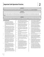
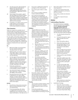
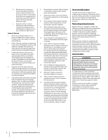
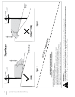
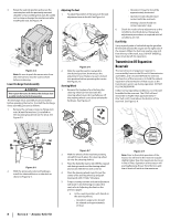
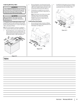
Assembly & Set-Up Thank You Thank you for purchasing this product. It was carefully engineered to provide excellent performance when properly operated and maintained. Please read this entire manual prior to operating the equipment. It instructs you how to safely and easily set up, operate and maintain your machine. Please be sure that you, and any other persons who will operate the machine, carefully follow the recommended safety practices at all times. Failure to do so could result in personal injury or property damage. All information in this manual is relative to the most recent product information available at the time. Review this manual frequently to familiarize yourself with the machine, its features and operation. Please be aware that this Operator's Manual may cover a range of product specifications for various models. Characteristics and features discussed and/or illustrated in this manual may not be applicable to all models. We reserve the right to change product specifications, designs and equipment without notice and without incurring obligation. 2 If applicable, the power testing information used to establish the power rating of the engine equipped on this machine can be found at www.opei.org or the engine manufacturer's web site. If you have any problems or questions concerning the machine, phone your local authorized service dealer or contact us directly. We want to ensure your complete satisfaction at all times. Throughout this manual, all references to right and left side of the machine are observed from the operating position. Contents of Crate • Zero-Turn Tractor (1) • Discharge Chute Assembly (1) • Operator's Manual (1) • Engine Operator's Manual (1) • Product Registration Card (1) † - If Equipped Note: This Operator's Manual covers several models. Tractor features may vary by model. Not all features in this manual are applicable to all tractor models and the tractor depicted may differ from yours. Note: All references in this manual to the left or right side and front or back of the tractor are from the operating position only. Exceptions, if any, will be specified. Note: Some components may come already assembled. If they are already assembled, skip ahead to the next step. Tractor Preparation Steering Wheel Column Install Operator's Seat Manually Moving the Tractor 1. Engage the transmission bypass rods, one on each side of the tractor, to move the tractor manually without starting it. The transmission bypass rods are located on the rear of the tractor, just inside each rear wheel. Engage the bypass rods by pulling each one out (a) and to the right (b) to lock it into place. See Figure 2-1. The steering wheel column (a) is tilted all the way back for shipping purposes. To tilt the steering wheel column (a) forward, rotate the steering column adjustment lever (b) counterclockwise, place the steering wheel column (a) in the desired position and then rotate the steering wheel column adjustment lever (b) clockwise to secure the steering wheel column in place. See Figure 2-2. To install the seat proceed as follows: Note: The seat is shipped with the seat switch and seat pan attached. 1. Cut any straps securing the seat assembly to the tractor. Remove any packing material. Note: Be careful not to cut the wiring harness connecting the seat and the seat switch. 2. Remove the two shoulder screws (a) and flange lock nuts (b) in the seat bracket (c) as shown in Figure 2-3. (a) aa b Figure 2-1 2. Disengage the bypass rods by reversing steps a & b after moving the tractor. See Figure 2-1. 3. Remove the deck wash system nozzle adapter from the manual bag and store for future use. (b) Figure 2-2 Note: Be sure that the steering column adjustment lever (b) is tight to prevent the steering wheel column (a) from moving when operating the machine. (a) (b) (b) (c) (a) Figure 2-3 7
-
 1
1 -
 2
2 -
 3
3 -
 4
4 -
 5
5 -
 6
6 -
 7
7 -
 8
8 -
 9
9 -
 10
10 -
 11
11 -
 12
12 -
13
-
14
-
15
-
16
-
17
-
18
-
19
-
20
-
21
-
22
-
23
-
24
-
25
-
26
-
27
-
28
-
29
-
30
-
31
-
32
-
33
-
34
-
35
-
36
-
37
-
38
-
39
-
40
-
41
-
42
-
43
-
44
 |
 |