Cub Cadet ZT1 42 Operation Manual - Page 22
Deck Installation, Replacing the Belt
 |
View all Cub Cadet ZT1 42 manuals
Add to My Manuals
Save this manual to your list of manuals |
Page 22 highlights
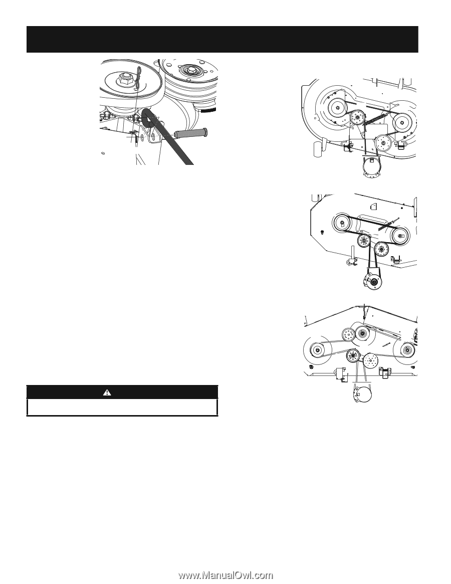
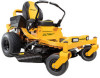
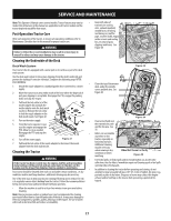
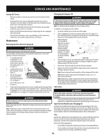
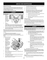
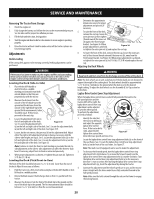
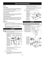
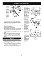
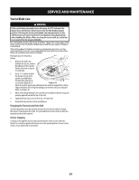
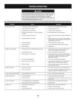
SERVICE AND MAINTENANCE b. Remove the third bow-tie pin (a) from the clevis pin (a) (b) that secures the front deck control rod (c) to the front deck lift bracket (d). Remove the clevis pin (b). (b) See Figure 42. c. Carefully manuever the (d) (c) deck out from beneath the Figure 42 tractor. Deck Installation Install the deck on the tractor as follows: 1. Carefully manuever the the deck under the tractor from the right side, lining up the deck hanger brackets and the deck lift arms on deck lift rod/deck release pin tractors and align the lift link brackets and front deck control rod with the deck lift brackets on three-pin tractors. 2. Once the deck is under the tractor, move the deck to the lowest mowing position. Note: To line the brackets up properly, it may be necessary to place a small block of wood under each side of the deck. 3. Re-install the applicable hardware for your tractor. 4. Make certain the 'V' belt is in the spindle pulleys on the deck; then route the belt rearward beneath the tractor frame, above the transmission tube(s), to the PTO pulley on the bottom of the engine. 5. Raise the deck to the position that provides the most horizontal run of the belt between the deck idler pulleys and the PTO pulley on the bottom of the engine. 6. Make certain the belt is in the spindle pulleys of the deck, and that the backside of the belt is against both the fixed and movable idler pulleys. 7. Sitting behind the tractor, facing forward, make certain the belt is not twisted; then reach beneath the tractor to grasp the belt and pull it toward the PTO pulley. WARNING Use caution to avoid pinching your fingers when rolling the belt onto the PTO pulley. 8. Pull the right side of the PTO belt rearward and place the narrow V-side of the PTO belt into the PTO pulley. See Figure 39. 9. While holding the PTO belt and PTO pulley together, rotate the PTO pulley to the left (See Figure 39). Continue holding and rotating the PTO pulley and PTO belt until the PTO belt is fully rolled into the PTO pulley. Note: Before using the tractor double-check the belt routing to make sure that the belt has been routed properly. Replacing the Belt 1. Remove the deck from beneath the tractor, (refer to Deck Removal). 2. Loosen, but do not remove the hardware on the right (a) and left idler pulley (b). Refer to Figure 43 for 42" decks, Figure 44 for 46" decks and Figure 45 for 50", 54" and 60" decks. Note: Take note of the position of the belt guards (c) to ensure they are properly re-installed. Note: On some decks it may be necessary to remove the spindle covers to remove and/ or install the new belt. To remove the spindle covers, remove the screws securing them to the deck. 3. Carefully remove the belt from around the idler pulleys (a & b) and the spindle pulleys (d). 42" Decks (d) (a) (d) (c) (c) (b) Figure 43 46" Decks (d) (a) (d) (c) (c) (b) 4. Install the new belt pulleys as shown and 50/54/60" reinstall the belt covers. Decks Figure 44 5. Place the belt around the idler pulleys removed in step 3 with the "V" side (d) (d) facing in. Once in place, reinstall all the hardware and tighten the flange (c) (c) (a) (b) lock nut to secure the assembly. 6. Route the belt as shown and then reinstall the deck (refer to Deck Installation) Figure 45 22
-
 1
1 -
2
-
3
-
4
-
5
-
6
-
7
-
8
-
9
-
10
-
11
-
12
-
13
-
14
-
15
-
16
-
 17
17 -
 18
18 -
 19
19 -
 20
20 -
 21
21 -
 22
22 -
 23
23 -
 24
24 -
 25
25 -
 26
26 -
 27
27 -
28
-
29
-
30
-
31
-
32
-
33
-
34
-
35
-
36
-
37
-
38
-
39
-
40
-
41
-
42
-
43
-
44
-
45
-
46
-
47
-
48
 |
 |