Cub Cadet ZT1 42 Operation Manual - Page 7
Assembly
 |
View all Cub Cadet ZT1 42 manuals
Add to My Manuals
Save this manual to your list of manuals |
Page 7 highlights
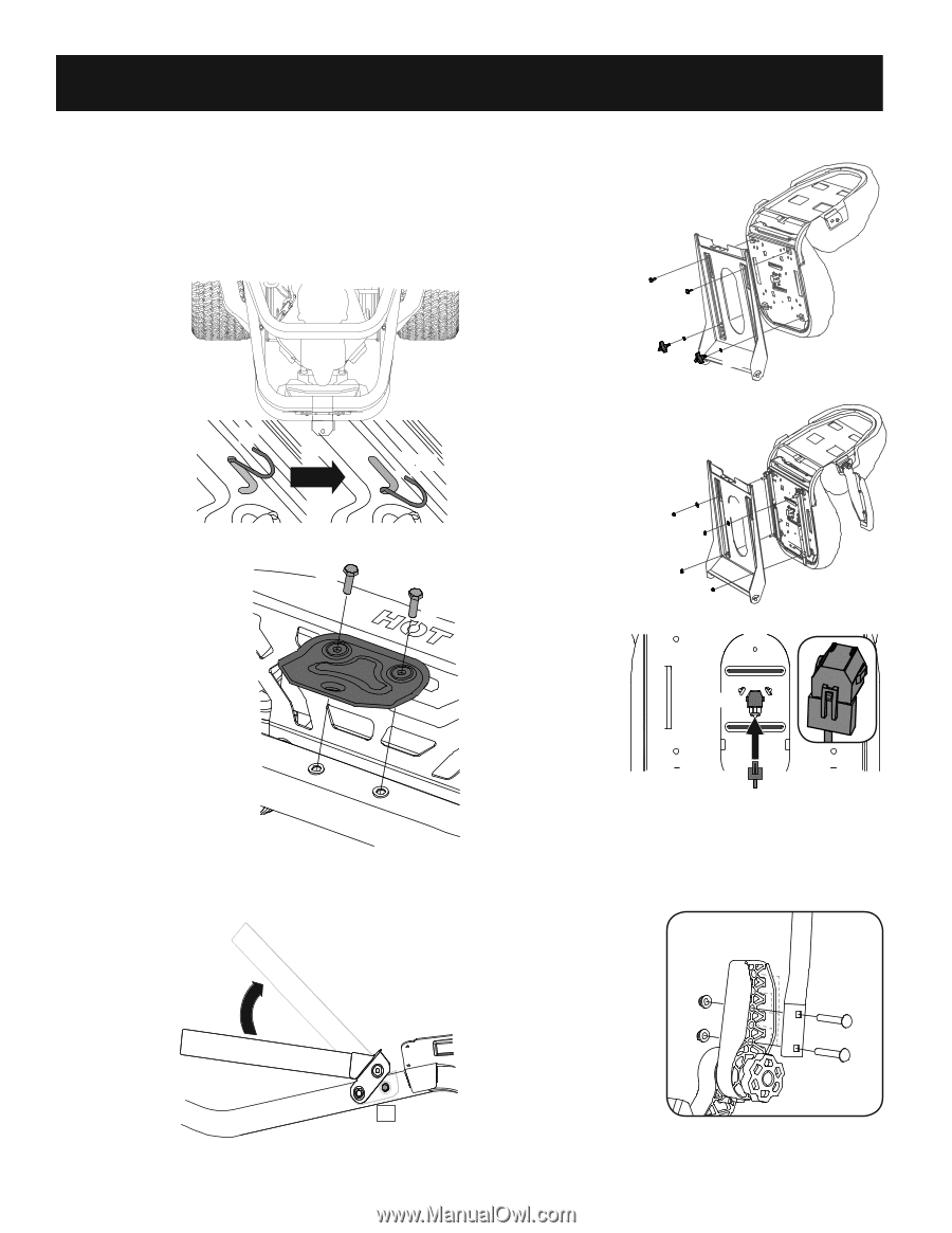
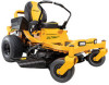
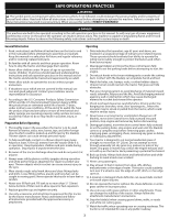
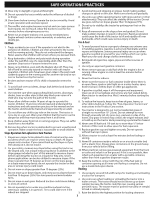
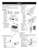
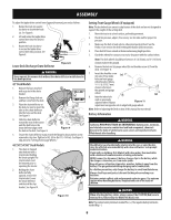
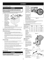
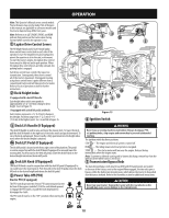
ASSEMBLY Note: This Operator's Manual covers several models. Tractor features may vary by model. Not all features in this manual are applicable to all tractor models and the tractor depicted may differ from yours. Note: All references in this manual to the left or right side and front or back of the tractor are from the operating position only. Exceptions, if any, will be specified. Preparation Manually Move the Tractor 1. To engage the transmission bypass rods, pull the rod back (a) and into lower section of "J" slot. Repeat on opposite side. See Figure 1. 2. After moving tractor, reverse step one (a) to disengage the bypass rods. (b) 3. Remove the deck wash system nozzle adapter from the manual bag, store for future use. Figure 1 Install Hitch (If necessary) (b) 1. Locate Hitch (a) and install on the rear of the frame using (b) the two hex washer screws (b) provided. See Figure 2. (a) Note: Hitch and hex washer screws will be the hardware pack. Figure 2 Reposition Upper Hoop (If necessary) Upper hoop may be positioned down for shipping purposes: 1. Remove the two hex (b) washer screws (a) partially installed on the frame. See Figure 3. (b) 2. Rotate the upper hoop (b) into position. See Figure 3. 3. Secure hoop in (a) place with the hex washer screws removed in step 1. Figure 3 Torque the hex washer screws to 159-239 in-lbs (18-27 N-m). Install Operator's Seat Knob Adjust or Lever Adjust 1. Cut any straps securing the seat assembly to the tractor. Remove all packing material. (a) Note: Be careful not to cut the seat wiring harness. (b) 2. Install the seat onto (b) the seat pan (a) using hardware provided. (c) a. For a Knob Adjust seat (d) (c) insert bolts (b) (d) in the rear holes Figure 4 and lock washer (c) and knobs (d) in the front. Tighten securely. See Figure 4. b. For a Lever Adjust (b) seat use flange (a) (b) lock nuts (a) and flat washers (b). (a) See Figure 5. 3. If necessary, securely (a) connect the seat switch wiring harness (a) to the (a) (c) seat switch (b). See Figure Figure 5 6. Secure excess wire away from (b) pinch points before continuing. Note: Tractor will not (b) operate without the (a) seat switch wiring harness connected. Position Lapbar Drive Control Levers (a) Figure 6 The lapbar drive control levers can be adjusted up/down and forward/backward for the operator's comfort. Three height positions are available and/or levers can be rotated forward or rearward using the knob. To adjust the lapbar drive control lever height, proceed as follows: 1. Remove the two carriage screws (a) and two flange lock nuts (b) that secure the lapbar drive control lever (c) to the (b) upper handle adjuster (d). See Figure 7. (b) Note: The multi-tool (if equipped) can be used to make this adjustment. 2. Move the lapbar drive control lever into one of the three available heights and secure in place with the carriage screws and flange lock nuts. See Figure 7. (d) (c) (a) (a) Figure 7 7
-
 1
1 -
 2
2 -
 3
3 -
 4
4 -
 5
5 -
 6
6 -
 7
7 -
 8
8 -
 9
9 -
 10
10 -
 11
11 -
 12
12 -
13
-
14
-
15
-
16
-
17
-
18
-
19
-
20
-
21
-
22
-
23
-
24
-
25
-
26
-
27
-
28
-
29
-
30
-
31
-
32
-
33
-
34
-
35
-
36
-
37
-
38
-
39
-
40
-
41
-
42
-
43
-
44
-
45
-
46
-
47
-
48
 |
 |