Cub Cadet ZT1 42 Operation Manual - Page 9
Connecting Battery Cables, Battery Removal, Charging the Battery, Adjusting the Seat
 |
View all Cub Cadet ZT1 42 manuals
Add to My Manuals
Save this manual to your list of manuals |
Page 9 highlights
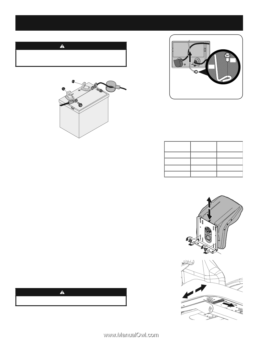
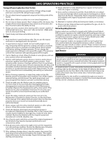
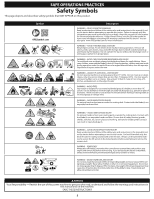
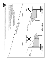
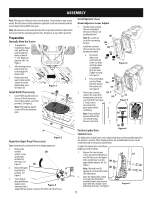
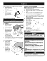
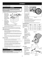
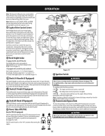
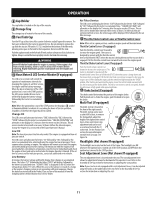
ASSEMBLY Connecting Battery Cables WARNING Always connect the positive lead to the battery before connecting the negative lead. This will prevent sparking or possible injury from an electrical short caused by contacting the tractor body with tools being used to connect the cables. For shipping reasons the factory may leave both battery cables disconnected from the terminals. To connect the battery cables, proceed as follows: 1. If present, remove the plastic cover from (b) the positive battery terminal. Attach the (b) (a) (c) red connector to the positive battery (a) terminal (+) using the bolt (a) and hex nut (b). See Figure 12. 2. If present, remove the plastic cover from the negative battery terminal and attach the black cable to the negative battery Figure 12 terminal (-) with the bolt (a) and hex nut (b). See Figure 12. 3. Position the red rubber boot (c) over the positive battery terminal to help protect it from corrosion. See Figure 12. Note: If the battery is put into service after date shown on top/side of battery, charge the battery as instructed in the Product Care section, prior to operating. Battery Maintenance • The battery is filled with battery acid and then sealed at the factory. However, even a "maintenance free" battery requires some maintenance to ensure its proper life cycle. • Spray the terminals and exposed wire with a battery terminal sealer, or coat the terminals with a thin coat of grease or petroleum jelly, to protect against corrosion. • Always keep the battery cables and terminals clean and free of corrosion. • Avoid tipping. Even a sealed battery will leak electrolyte when tipped. Battery Storage • When storing the tractor for extended periods, disconnect the negative battery cable. It is not necessary to remove the battery. • All batteries discharge during storage. Keep the exterior of the battery clean, especially the top. A dirty battery will discharge more rapidly. • The battery must be stored with a full charge. A discharged battery can freeze sooner than a charged battery. A fully charged battery will store longer in cold temperatures than hot. 1. Remove the hex washer screw (a) securing the battery hold-down bracket (b) to the frame. Then flip the battery hold-down bracket (b) up to free the battery. See Figure 13. (a) (b) 2. Remove the hex cap screw and sems nut securing the black negative battery lead to the negative battery post (marked NEG). Move the cable away from the negative battery post. Figure 13 3. Remove the hex cap screw and sems nut securing the red positive battery lead to the positive battery post (marked POS). 4. Carefully lift the battery out of the tractor. 5. Install the battery by repeating the above steps in the reverse order. Charging the Battery Test and, if necessary, recharge the battery after the tractor has been stored for a period of time. Voltmeter Reading 12.7 12.4 State of Charge 100% 75% Charging Time Full Charge 90 Min. • A voltmeter 12.2 or load tester should read 12.0 12.6 volts (DC) or higher across the battery terminals. See Figure 14. 50% 25% Figure 14 180 Min. 280 Min. • Charge the battery with a 12-volt battery charger at a MAXIMUM rate of 10 amps. Adjusting the Seat Knob Adjust 1. Remove the knobs (a). 2. Slide the seat up or down into the desired position. 3. Replace the knobs into one (a) of the four hole settings and tighten securely. See Figure 15. (a) Figure 15 • Recharge the battery before returning to service. Although the tractor may start, the engine charging system may not fully recharge the battery. Battery Removal WARNING Battery posts, terminals and related accessories contain lead and lead compounds. Wash hands after handling. The battery is located beneath the seat frame. To remove the battery: Lever Adjust 1. Push left and hold the seat adjustment lever to adjust the seat position. 2. Slide seat forward or rearward to desired position. 3. Release the adjustment lever. Ensure seat is locked into position before operation. See Figure 16. 9 Figure 16
-
 1
1 -
2
-
3
-
 4
4 -
 5
5 -
 6
6 -
 7
7 -
 8
8 -
 9
9 -
 10
10 -
 11
11 -
 12
12 -
 13
13 -
 14
14 -
15
-
16
-
17
-
18
-
19
-
20
-
21
-
22
-
23
-
24
-
25
-
26
-
27
-
28
-
29
-
30
-
31
-
32
-
33
-
34
-
35
-
36
-
37
-
38
-
39
-
40
-
41
-
42
-
43
-
44
-
45
-
46
-
47
-
48
 |
 |