Cub Cadet ZT1 42 Operation Manual - Page 8
Lower Deck Discharge Chute Deflector, Deck Models, 50/54/60 Deck Models, Setting Front Gauge - accessories
 |
View all Cub Cadet ZT1 42 manuals
Add to My Manuals
Save this manual to your list of manuals |
Page 8 highlights
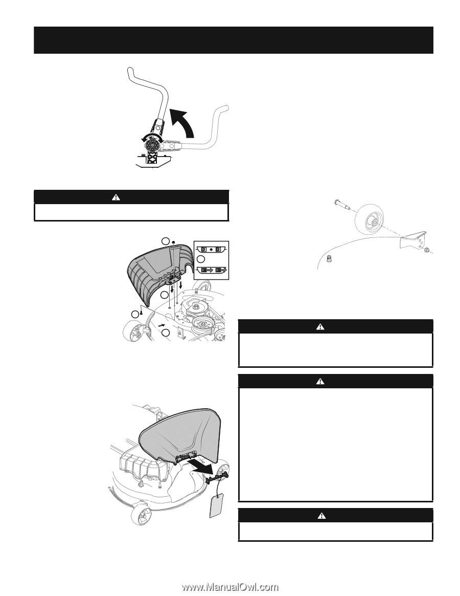
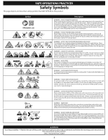
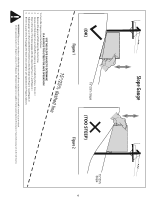
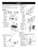
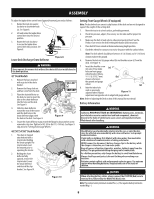
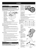
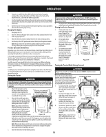
ASSEMBLY To adjust the lapbar drive control levers forward/rearward, proceed as follows: 1. Rotate the knob (a) counterclockwise to loosen the knob (a). See Figure 8. 2. Lift and rotate the lapbar drive control lever into the desired position. 3. Rotate the knob clockwise to secure the lapbar drive control lever into position. See Figure 8. (a) Lower Deck Discharge Chute Deflector Figure 8 WARNING Never operate the mower deck without the chute deflector installed and in the down position. 42" Deck Models 1. Remove the keys attached with a zip tie to the chute bracket. 2. Remove the flange lock nut and hex screw from the deck. 5 4 3. Place the chute deflector on the deck, be sure to insert the tabs on the chute deflector 3 into the holes on the deck. See Figure 9. 5 4. Slide the chute deflector toward the rear of the tractor until the bolt hole in the chute deflector aligns with the hole in the deck. See Figure 9. 4 Figure 9 5. Secure the chute deflector in place with the flange lock nut and hex screw removed in step two. Tighten to 102-124 in-lbs (11.5-14 N-m). See Figure 9. Skip ahead to "Setting Front Gauge Wheels." 46"/50"/54"/60" Deck Models 1. The chute is shipped attached and with a stop bracket holding the chute upright. The stop brackets must be removed prior to operating the tractor. 2. Holding the chute deflector fully upward, remove the stop bracket. Lower the chute deflector and discard the stop bracket. See Figure 10. Figure 10 Setting Front Gauge Wheels (If equipped) Note: The deck wheels are an anti-scalp feature of the deck and are not designed to support the weight of the cutting deck. 1. Move the tractor to a level surface, preferably pavement. 2. Check tire pressure, adjust, if necessary. See tire side wall for proper tire pressure. 3. Make sure the deck is level side-to-side and properly pitched. See the Product Care section for deck leveling information and instructions. 4. Place deck lift lever or knob in the desired mowing height position. 5. Check the wheels for contact or excessive clearance with the surface below. Note: The deck wheels should have between ¼" (6.35mm) and ½" (12.7mm) clearance above the ground. 6. Remove the lock nut (a) gauge wheel (b) and shoulder screw (c) from the deck. See Figure 11. 7. Insert the shoulder screw into one of four index (c) holes on front gauge wheel bracket. Allow a 6.35-12.7 mm) (b) clearance between the ground and gauge wheel. (a) 8. Note the index hole used on previously adjusted wheel. Repeat Figure 11 adjustment on opposite side to align both gauge wheels. Note: Refer to Adjusting the Deck section of this manual for more detail. Battery Information WARNING California PROPOSITION 65 WARNING: Battery posts, terminals, and related accessories contain lead and lead compounds, chemicals known to the State of California to cause cancer and reproductive harm. Wash hands after handling. WARNING Should battery acid accidentally splatter into the eyes or onto the skin, rinse the affected area immediately with clean cold water. Seek prompt medical attention. If acid spills on clothing, first dilute it with clean water, then neutralize with a solution of ammonia/water or baking soda/water. NEVER connect (or disconnect) battery charger clips to the battery while the charger is turned on, as it can cause sparks. Keep all sources of ignition (cigarettes, matches, lighters) away from the battery. The gas generated during charging can be combustible. As a further precaution, only charge the battery in a well ventilated area. Always shield eyes and protect skin and clothing when working near batteries. Batteries contain sulfuric acid and may emit explosive gases. Use extreme caution when handling batteries. Keep batteries out of the reach of children. CAUTION When attaching battery cables, always connect the POSITIVE (Red) wire to terminal first, followed by the NEGATIVE (Black) wire. Note: The positive battery terminal is marked Pos. (+). The negative battery terminal is marked Neg. (-). 8
-
 1
1 -
2
-
 3
3 -
 4
4 -
 5
5 -
 6
6 -
 7
7 -
 8
8 -
 9
9 -
 10
10 -
 11
11 -
 12
12 -
 13
13 -
14
-
15
-
16
-
17
-
18
-
19
-
20
-
21
-
22
-
23
-
24
-
25
-
26
-
27
-
28
-
29
-
30
-
31
-
32
-
33
-
34
-
35
-
36
-
37
-
38
-
39
-
40
-
41
-
42
-
43
-
44
-
45
-
46
-
47
-
48
 |
 |