Cub Cadet ZTS1 42 Operation Manual - Page 11
Battery Information
 |
View all Cub Cadet ZTS1 42 manuals
Add to My Manuals
Save this manual to your list of manuals |
Page 11 highlights
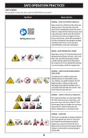
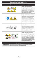
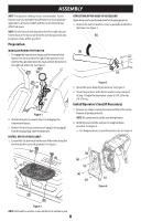
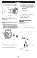
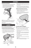
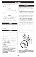
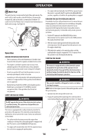
ASSEMBLY 6. Remove the lock nut (a), gauge wheel (b) and shoulder screw (c) from the deck. See Figure 11. (c) (b) CONNECTING BATTERY CABLES WARNING Always connect the positive lead to the battery before connecting the negative lead. This will prevent sparking or possible injury from an electrical short caused by contacting the tractor body with tools being used to connect the cables. For shipping reasons the factory may leave both battery cables (a) disconnected from the terminals. To connect the battery cables, proceed as follows: Figure 11 7. Insert the shoulder screw (c) into one of four index holes on the deck wheel bracket. Allow a 1⁄4-1⁄2" (6.35-12.7 mm) clearance between the ground and gauge wheel. See Figure 11. 8. Note the index hole used on previously adjusted wheel. Repeat adjustment on opposite side to align both gauge wheels. Battery Information WARNING California PROPOSITION 65 WARNING: Battery posts, terminals, and related accessories contain lead and lead compounds, chemicals known to the State of California to cause cancer and reproductive harm. Wash hands after handling. NOTE: Wiring harness should lay on top of battery hold down rod, otherwise damage to the wiring harness may result. See Figure 13 on page 12. 1. Remove the factory installed hex screws (a) and square nuts (b) located either on the end of the wiring harness or in the bag with this manual. Retain the hardware for later instructions. See Figure 12. 2. Remove the plastic cover (c), if present, from the positive battery terminal (d) and attach the red cable (e) to the positive battery terminal (d) with one of the hex screws (a) and square nuts (b), from Step 1. Use a Philips screw driver. See Figure 12. 3. Position the red rubber boot over the positive battery terminal to help protect it from corrosion. See inset in Figure 12. WARNING Should battery acid accidentally splatter into the eyes or onto the skin, rinse the affected area immediately with clean cold water. Seek prompt medical attention. If acid spills on clothing, first dilute it with clean water, then neutralize with a solution of ammonia/water or baking soda/water. NEVER connect (or disconnect) battery charger clips to the battery while the charger is turned on, as it can cause sparks. Keep all sources of ignition (cigarettes, matches, lighters) away from the battery. The gas generated during charging can be combustible. As a further precaution, only charge the battery in a well ventilated area. Always shield eyes and protect skin and clothing when working near batteries. Batteries contain sulfuric acid and may emit explosive gases. Use extreme caution when handling batteries. Keep batteries out of the reach of children. The battery may present a risk of fire or chemical burn if misused. Do NOT open, disassemble, overheat, or incinerate the battery. 4. Remove the plastic cover (c), if present, from the negative battery terminal (f) and attach the black cable (g) to the negative battery terminal (f) with the remaining hex screw (a) and square nut (b). See Figure 12. (c) (e) (a) (c) (b) (d) (a) (f) (b) (g) Figure 12 NOTE: If the battery is put into service after date shown on top/ side of battery, charge the battery as instructed in Charging the Battery, prior to operating. NOTE: The positive battery terminal is marked Pos. (+). The negative battery terminal is marked Neg. (-). 11
-
 1
1 -
2
-
3
-
4
-
5
-
 6
6 -
 7
7 -
 8
8 -
 9
9 -
 10
10 -
 11
11 -
 12
12 -
 13
13 -
 14
14 -
 15
15 -
 16
16 -
17
-
18
-
19
-
20
-
21
-
22
-
23
-
24
-
25
-
26
-
27
-
28
-
29
-
30
-
31
-
32
-
33
-
34
-
35
-
36
-
37
-
38
-
39
-
40
-
41
-
42
-
43
-
44
-
45
-
46
-
47
-
48
-
49
-
50
-
51
-
52
-
53
-
54
-
55
-
56
-
57
-
58
-
59
-
60
-
61
-
62
-
63
-
64
-
65
-
66
-
67
-
68
-
69
-
70
-
71
-
72
-
73
-
74
-
75
-
76
-
77
-
78
-
79
-
80
-
81
-
82
-
83
-
84
-
85
-
86
-
87
-
88
-
89
-
90
-
91
-
92
-
93
-
94
-
95
-
96
 |
 |
