D-Link DE-1824EI User Guide - Page 15
External Features and Indicators, Front and Back Panel Layouts
 |
UPC - 790069217593
View all D-Link DE-1824EI manuals
Add to My Manuals
Save this manual to your list of manuals |
Page 15 highlights
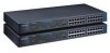
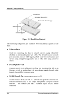
10BASE-T Stackable Hubs 2 2 EXTERNAL FEATURES AND INDICATORS This chapter introduces the controls and connectors on the front and rear panels of the hub, and explains the front panel display in detail. Figures 2-1, 2-2 and 2-3 show the layouts of the front panel, rear panel, and display of the stackable hubs. Note that there are variations in the appearances of the front and back panels between hubs in the series. Only the 24-port models are depicted in this User's Guide. Front and Back Panel Layouts LED Panel Uplink Switch 10BASE-T Ports Figure 2 -1 Front Panel Layout Setting Up the Hub 2-1
-
 1
1 -
2
-
3
-
4
-
5
-
6
-
7
-
8
-
9
-
 10
10 -
 11
11 -
 12
12 -
 13
13 -
 14
14 -
 15
15 -
 16
16 -
 17
17 -
 18
18 -
 19
19 -
 20
20 -
21
-
22
-
23
-
24
-
25
-
26
-
27
-
28
-
29
-
30
-
31
-
32
-
33
-
34
-
35
-
36
-
37
-
38
-
39
-
40
-
41
-
42
-
43
-
44
-
45
-
46
-
47
-
48
-
49
-
50
-
51
-
52
-
53
-
54
-
55
-
56
-
57
-
58
-
59
-
60
-
61
-
62
-
63
-
64
-
65
-
66
-
67
-
68
-
69
-
70
-
71
-
72
-
73
-
74
-
75
-
76
-
77
-
78
-
79
-
80
-
81
-
82
-
83
-
84
-
85
-
86
-
87
 |
 |
10BASE-T Stackable Hubs
2
2
E
XTERNAL
F
EATURES
AND
I
NDICATORS
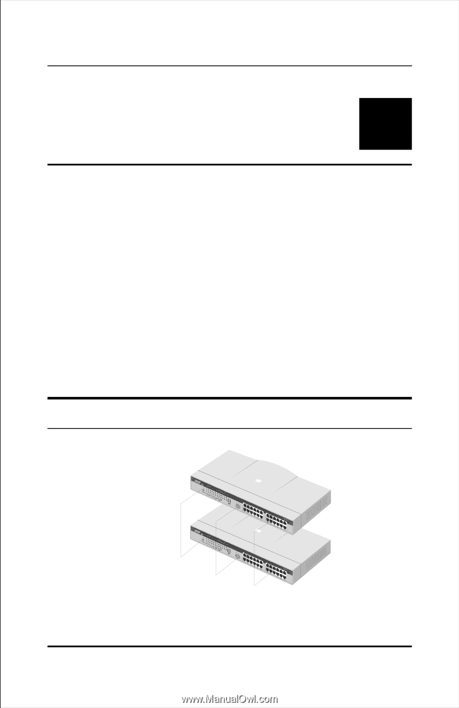
This chapter introduces the controls and connectors on the front and rear
panels of the hub, and explains the front panel display in detail.
Figures 2-1, 2-2 and 2-3 show the layouts of the front panel, rear panel, and
display of the stackable hubs.
Note that there are variations in the
appearances of the front and back panels between hubs in the series. Only
the 24-port models are depicted in this
User's Guide
.
Front and Back Panel Layouts
Uplink Switch
10BASE-T Ports
LED Panel
Figure 2 -1
Front Panel Layout
Setting Up the Hub
2-1