D-Link DGS-1510 Quick Install Guide - Page 20
Power On (AC Power)
 |
View all D-Link DGS-1510 manuals
Add to My Manuals
Save this manual to your list of manuals |
Page 20 highlights
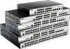
DGS-1510 Series Gigabit Ethernet SmartPro Switch Hardware Installation Guide can be uplinked with various other switches across a gigabit network. The SFP ports support data rates of up to 1Gbit/s and the SFP+ ports support data rates of up to 10Gbit/s. See the figure below for installing the transceiver in the transceiver port on the Switch. Figure 2-4 Inserting fiber-optic transceivers into a Switch For a full list of supported transceivers, compatible with this switch series, refer to Port Functions. NOTE: Only use pluggable optical modules and Direct-Attach Cables (DAC) that meet the following regulatory requirements: • Class 1 Laser Product • UL and/or CSA registered component for North America • FCC 21 CFR Chapter 1, Sub-chapter J in accordance with FDA & CDRH requirements • IEC/EN 60825-1/-2: 2007 2nd edition or later, European Standard Power On (AC Power) Plug one end of the AC power cord into the power socket of the Switch and the other end into the local power source outlet. After the system powered on, the LED's blink green to indicate that the system is booting up. Power Failure (AC Power) In the event of a power failure, just as a precaution, unplug the power cord from the Switch. After the power returns, plug the power cord back into the power socket of the Switch. 20
-
 1
1 -
2
-
3
-
4
-
5
-
6
-
7
-
8
-
9
-
10
-
11
-
12
-
13
-
14
-
 15
15 -
 16
16 -
 17
17 -
 18
18 -
 19
19 -
 20
20 -
 21
21 -
 22
22 -
 23
23 -
 24
24 -
 25
25 -
26
-
27
-
28
-
29
-
30
-
31
-
32
-
33
-
34
-
35
-
36
-
37
-
38
-
39
-
40
-
41
-
42
-
43
-
44
-
45
-
46
-
47
-
48
-
49
-
50
-
51
-
52
-
53
-
54
-
55
-
56
-
57
-
58
-
59
-
60
-
61
-
62
-
63
-
64
-
65
-
66
 |
 |
