D-Link DMS-3130-30TS Product Manual
D-Link DMS-3130-30TS Manual
 |
View all D-Link DMS-3130-30TS manuals
Add to My Manuals
Save this manual to your list of manuals |
D-Link DMS-3130-30TS manual content summary:
- D-Link DMS-3130-30TS | Product Manual - Page 1
Hardware Installation Guide Product Model: DMS-3130 Series Layer 3 Stackable Managed Switch Release 1.00 - D-Link DMS-3130-30TS | Product Manual - Page 2
DMS-3130 Series Layer 3 Stackable Managed Switch Hardware Installation Guide Information in this document is subject to change without notice. Reproduction in any manner whatsoever, without the written permission of D-Link Corporation, is strictly forbidden. Trademarks used in this text: D-Link and - D-Link DMS-3130-30TS | Product Manual - Page 3
DMS-3130 Series Layer 3 Stackable Managed Switch Hardware Installation Guide The machine can only be used in a restricted access location and has installation instructions be referred to as the Switch throughout this manual. Typographical Conventions Convention Boldface Font Initial capital letter - D-Link DMS-3130-30TS | Product Manual - Page 4
DMS-3130 Series Layer 3 Stackable Managed Switch Hardware Installation Guide The product does not operate correctly when the operating instructions are correctly followed. General safety cautions: • Keep . If the system gets wet contact your trained service provider. • Do not push any objects into - D-Link DMS-3130-30TS | Product Manual - Page 5
DMS-3130 Series Layer 3 Stackable Managed Switch Hardware Installation Guide • Use only approved power cable(s). If you la batterie est remplacée par un type incorrect. Jetez les piles usagées selon les instructions CAUTION: Shock hazard This product is intended to be use with a UL Listed Optical - D-Link DMS-3130-30TS | Product Manual - Page 6
DMS-3130 Series Layer 3 Stackable Managed Switch Hardware Installation Guide pièce concernée ou contactez votre prestataire de services agréé. • Endommagement du câble d'alimentation, produit ne fonctionne pas correctement lorsque les instructions d'utilisation sont correctement suivies. Précautions - D-Link DMS-3130-30TS | Product Manual - Page 7
DMS-3130 Series Layer 3 Stackable Managed Switch Hardware Installation Guide chaud, system, as well as to various peripherals or supporting hardware: CAUTION: Installing systems in a rack without not step on or stand on any component when servicing other components in a rack. CAUTION: Never defeat - D-Link DMS-3130-30TS | Product Manual - Page 8
DMS-3130 Series Layer 3 Stackable Managed Switch Hardware Installation Guide CAUTION: The system chassis must be positively grounded to the rack cabinet frame. Do not attempt to connect power to the system until grounding cables - D-Link DMS-3130-30TS | Product Manual - Page 9
DMS-3130 Series Layer 3 Stackable Managed Switch Hardware Installation Guide Table of Contents Intended Readers ...3 Typographical Conventions ...3 Notes and Cautions ...4 Safety/Sécurité...4 Safety Instructions ...11 2. Hardware Components ...14 DMS-3130-30TS Switch ...14 Front Panel Components...14 - D-Link DMS-3130-30TS | Product Manual - Page 10
DMS-3130 Series Layer 3 Stackable Managed Switch Hardware Installation Guide Connecting to the MGMT Port ...38 Connecting using SNMP ...38 Traps ...39 Management Information Redundant Power Supply (RPS) Cable ...50 CE RED Compliance Statement ...51 Additional Notice ...51 Technical Support ...52 x - D-Link DMS-3130-30TS | Product Manual - Page 11
the SFP28 ports may be used to physically stack the Switch with other switches in this series. The D-Link DMS-3130 Series includes the following switches: • DMS-3130-30TS supports twenty-four 2.5 Gigabit RJ45 ports (100 Megabit/1 Gigabit/2.5 Gigabit), two 10 Gigabit RJ45 ports (100 Megabit/1 Gigabit - D-Link DMS-3130-30TS | Product Manual - Page 12
DMS-3130 Series Layer 3 Stackable Managed Switch Hardware Installation Guide Features that can be found on this switch are: • Virtual Stacking. D-Link (RIPv1/RIPv2), and RIPng • Class of Service (CoS) • Two-rate Three-color Marker Support (IPv4/IPv6) • Cable Diagnostics • 802.3ah Ethernet Link OAM - D-Link DMS-3130-30TS | Product Manual - Page 13
DMS-3130 Series Layer 3 Stackable Managed Switch Hardware Installation Guide • Network Time Protocol (NTP) IPv4/IPv6 • Simple Network Time Protocol (SNTP) IPv4/IPv6 • Link Layer Discovery Protocol (LLDP), and LLDP-MED • User Account Privilege for Management Access • Command Line Interface (CLI) • - D-Link DMS-3130-30TS | Product Manual - Page 14
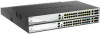
Guide 2. Hardware Components This chapter describes the front, rear, and side panel components of all switches in the series. DMS-3130-30TS Switch DMS-3130-30PS Switch DMS-3130-30TS Switch Front Panel Components The front panel of DMS-3130-30TS 25 Gbps wire-speed and support a wide collection of SFP+ - D-Link DMS-3130-30TS | Product Manual - Page 15
Series Layer 3 Stackable Managed Switch Hardware Installation Guide LED Console MGMT RPS Fan Error USB Link/Act/Speed LEDs Figure 2-2 LED indicators for the DMS-3130-30TS Description This LED will light solid green after the Switch has been powered on successfully. This LED will be off when the - D-Link DMS-3130-30TS | Product Manual - Page 16
DMS-3130 Series Layer 3 Stackable Managed Switch Hardware Installation Guide Description green when a 25 Gbps port is active or blink amber when a 10 Gbps port is active. The LED will be off when there is no link Figure 2-3 Rear panel view of the DMS-3130-30TS Components that can be found on the - D-Link DMS-3130-30TS | Product Manual - Page 17
Guide Figure 2-4 Side panels of the DMS-3130-30TS DMS-3130-30PS Switch Front Panel Components The front panel of DMS-3130-30PS features a variety of LED indicators and ports. Figure 2-5 Front panel view of the DMS-3130 wire-speeds and support a wide collection of SFP+ or SFP28 transceivers. 17 - D-Link DMS-3130-30TS | Product Manual - Page 18
DMS-3130 Series Layer 3 Stackable Managed Switch Hardware Installation Guide For a complete list of SFP transceivers Fan Err, USB, Link/Act indicators for all the ports, and Stack ID. Figure 2-6 LED indicators for the DMS-3130-30PS LED Power Console MGMT RPS Fan Error USB Link/Act/Speed LEDs & PoE - D-Link DMS-3130-30TS | Product Manual - Page 19
DMS-3130 Series Layer 3 Stackable Managed Switch Hardware Installation Guide Description active or blink amber when a 100/1000 Mbps port is active. The LED will be off when there is no link and G. The stacking ID (1 to 9) can be assigned manually by the user or automatically by the system. The letter - D-Link DMS-3130-30TS | Product Manual - Page 20
DMS-3130 Series Layer 3 Stackable Managed Switch Hardware Installation Guide Component Switch GND Description Use an electrical grounding wire and connect one end of the wire which could lead to system failure or even severely damaged components. Figure 2-8 Side panels of the DMS-3130-30PS 20 - D-Link DMS-3130-30TS | Product Manual - Page 21
to sunlight. Installing the Switch without a Rack This section is used to guide the user through installing the Switch in an area other than a switch rack Attaching rubber feet to the Switch DMS-3130-30TS Install the Switch on a sturdy, level surface that can support the weight of the Switch (see - D-Link DMS-3130-30TS | Product Manual - Page 22
DMS-3130 Series Layer 3 Stackable Managed Switch Hardware Installation Guide Installing the Switch in a Standard 19" Rack This section is used to guide connect various other networking devices to this switch that do not support the standard RJ45 wiring connection. These ports are generally used to - D-Link DMS-3130-30TS | Product Manual - Page 23
DMS-3130 Series Layer 3 Stackable Managed Switch Hardware Installation Guide The figure below illustrates how to properly insert SFP28 transceivers into the Switch's SFP28 ports. Figure 3-4 Inserting transceivers into the transceiver ports The SFP28 ports support transceiver form factors: SFP28 and - D-Link DMS-3130-30TS | Product Manual - Page 24
DMS-3130 Series Layer 3 Stackable Managed Switch Hardware Installation Guide Figure 3-5 Insert Tie Wrap into the Switch 2. Plug the AC power cord into the power socket of the Switch. Figure 3-6 Connect the power cord to - D-Link DMS-3130-30TS | Product Manual - Page 25
DMS-3130 Series Layer 3 Stackable Managed Switch Hardware Installation Guide to conform to the wattage requirements of D-Link's Ethernet and Gigabit switches. The external RPS RPS provides an affordable cost, simple solution to the problem of an inadvertent failure of the internal power supply of - D-Link DMS-3130-30TS | Product Manual - Page 26
DMS-3130 Series Layer 3 Stackable Managed Switch Hardware Installation Guide sources. Please disconnect all the power cords before servicing. DPS-500A Series Redundant Power Supply Unit this section only applies to DMS-313030TS. Figure 3-10 Connecting a DMS-3130-30TS Series Switch to the DPS-500A - D-Link DMS-3130-30TS | Product Manual - Page 27
DMS-3130 Series Layer 3 Stackable Managed Switch Hardware Installation Guide NOTE: This rack-mount chassis supports the following RPS units: DPS-500A/DPS-500DC. The following diagram illustrates how a DPS-500A is installed into a DPS-800. Figure 3-11 Install the DPS- - D-Link DMS-3130-30TS | Product Manual - Page 28
DMS-3130 Series Layer 3 Stackable Managed Switch Hardware Installation Guide 4. Switch Connections Switch to an End Node Switch to pair Category 6/6a/7 UTP/STP cable. • Connect a fiber, uplink, switch port supporting an optical fiber uplink to the Switch's SFP28 ports via fiber optical cabling. 28 - D-Link DMS-3130-30TS | Product Manual - Page 29
Hardware Installation Guide Figure 4-2 Connecting the Switch to another switch/hub Switch Stacking The DMS-3130 series supports stacking up to overall reliability, serviceability, and availability. • Duplex Chain - The Duplex Chain topology stacks switches together in a chain-link format. Using - D-Link DMS-3130-30TS | Product Manual - Page 30
DMS-3130 Series Layer 3 Stackable Managed Switch Hardware Installation Guide Figure 4-3 2-Port Duplex Chain stacking topology (SFP28 ports) 30 - D-Link DMS-3130-30TS | Product Manual - Page 31
DMS-3130 Series Layer 3 Stackable Managed Switch Hardware Installation Guide Figure 4-4 4-Port Duplex Chain stacking topology (SFP28 ports) 31 - D-Link DMS-3130-30TS | Product Manual - Page 32
DMS-3130 Series Layer 3 Stackable Managed Switch Hardware Installation Guide The figures below illustrate how switches can be stacked in a Duplex Ring formation using optical fiber cables connected to SFP28 transceivers or DAC with SFP28 - D-Link DMS-3130-30TS | Product Manual - Page 33
DMS-3130 Series Layer 3 Stackable Managed Switch Hardware Installation Guide Figure 4-6 4-port Duplex Ring stacking topology (SFP28 ports) 33 - D-Link DMS-3130-30TS | Product Manual - Page 34
DMS-3130 Series Layer 3 Stackable Managed Switch Hardware Installation Guide Switch to a Server The Switch is ideal for connecting to a network backbone, server, or server farm. The RJ45 ports operate at a speed of 100/1000 - D-Link DMS-3130-30TS | Product Manual - Page 35
switch management features. For more detailed information about the CLI, refer to the DMS-3130 Series CLI Reference Guide. SNMP-based Management The Switch can be managed with a SNMP-compatible console program. The Switch supports SNMP v1, SNMPv2c and SNMPv3. The SNMP agent decodes the incoming SNMP - D-Link DMS-3130-30TS | Product Manual - Page 36
DMS-3130 Series Layer 3 Stackable Managed Switch Hardware Installation Guide Switch for the First Time The Switch supports user-based security that can prevent unauthorized users DMS-3130-30TS Gigabit Ethernet Switch Switch> Command Line Interface Firmware: Build 1.00.B009 Copyright(C) 2018 D-Link - D-Link DMS-3130-30TS | Product Manual - Page 37
DMS-3130 Series Layer 3 Stackable Managed Switch Hardware Installation Guide Creating a User Account One of the first and most important tasks will be to create user accounts. Logging in using a predefined administratorlevel username will give - D-Link DMS-3130-30TS | Product Manual - Page 38
DMS-3130 Series Layer 3 Stackable Managed Switch Hardware Installation Guide Switch#show ip interface mgmt 0 mgmt_ipif 0 is enabled, Link status is up IP address is 192.168.0.1/24 Gateway is detect potential problems in the Switch, switch group, or network. Managed devices that support SNMP include - D-Link DMS-3130-30TS | Product Manual - Page 39
DMS-3130 Series Layer 3 Stackable Managed Switch Hardware Installation Guide In SNMPv1 and SNMPv2c, user network management software. In addition to the standard MIB-II, the Switch also supports its own proprietary enterprise MIB as an extended Management Information Base. The proprietary - D-Link DMS-3130-30TS | Product Manual - Page 40
DMS-3130 Series Layer 3 Stackable Managed Switch Hardware Installation Guide Web-based Switch Configuration Introduction with the Switch using the HTTP or HTTPS (SSL) protocol. The following web browsers are supported: • Internet Explorer • Firefox • Google Chrome • Safari Logging into the Web UI To - D-Link DMS-3130-30TS | Product Manual - Page 41
DMS-3130 Series Layer 3 Stackable Managed Switch Hardware Installation Guide NOTE: After a user account was created, functions, including port monitoring, are accessible from here. Click the D-Link logo to go to the D-Link website. This area displays a file explorer-type menu tree with all - D-Link DMS-3130-30TS | Product Manual - Page 42
DMS-3130 Series Layer 3 Stackable Managed Switch Hardware Installation Guide Web and configured in this folder. Features regarding the Quality of Service functionality of the Switch can be viewed and configured in regarding the D-Link Green Technology can be viewed and configured in this folder. - D-Link DMS-3130-30TS | Product Manual - Page 43
DMS-3130 Series Layer 3 Stackable Managed Switch Hardware Installation Guide Stacking Units: Up to 9 switches in a stack Backup Master Support: Yes UTP/STP Category 3, 4, 5 for 10BASE-T UTP/STP 100~240 VAC, 50~60 Hz Available on DMS-3130-30TS only. One connector in back to install optional - D-Link DMS-3130-30TS | Product Manual - Page 44
DMS-3130-30TS: 4 MBytes per device DMS-3130-30PS: 4 MBytes per device 9K Bytes (9216 Bytes) DMS-3130-30TS: 360 Gbps DMS-3130-30PS: 400 Gbps DMS-3130-30TS: 125 Mpps DMS-3130-30PS: 161 Mpps 8 Priority Queues per port. Supports 32K (32,768) MAC addresses IPv4 and IPv6: Max.1024 entries Supports D-Link - D-Link DMS-3130-30TS | Product Manual - Page 45
DMS-3130 Series Layer 3 Stackable Managed Switch Hardware Installation Guide Location LED Console Fan Err RPS USB Stacking ID (7-segment LED) LED Per 10/100/1000 Mbps Port Link/Act/Speed LED Per 2.5 Gbps Port Link/Act/Speed PSE (for DMS3130-30PS only) LED Per 5 Gbps Port (for DMS-313030PS - D-Link DMS-3130-30TS | Product Manual - Page 46
DMS-3130 Series Layer 3 Stackable Managed Switch Hardware Installation Guide Location LED PSE LED Per 10 Gbps Port Link/Act/Speed LED per SFP28/SFP+ Port Link/Act/Speed Color Amber • IEEE 802.3at compliance • IEEE 802.3bt compliance Support Full-Duplex operations • IEEE 802.3x Flow Control - D-Link DMS-3130-30TS | Product Manual - Page 47
DMS-3130 Series Layer 3 Stackable Managed Switch Hardware Installation Guide Feature SFP+ Ports SFP28 Ports Description Compliant with the following standards: • IEEE 802.3ae compliance SFP+ Transceivers Supported: • DEM-431XT: 10GBASE-SR Multi-mode, OM1:33M/OM2:82M/OM3:300M (w/o DDM) • DEM-432XT: - D-Link DMS-3130-30TS | Product Manual - Page 48
DMS-3130 Series Layer 3 Stackable Managed Switch Hardware Installation Guide Appendix B - Cables and Connectors Ethernet Cable When connecting the Switch to another switch, a bridge or hub, a straight-through Cat5/5e/6a/7 cable is necessary. Please - D-Link DMS-3130-30TS | Product Manual - Page 49
DMS-3130 Series Layer 3 Stackable Managed Switch Hardware Installation Guide Console Cable (RJ45 to RS-232) A console cable is used to connect to the RJ45 console port of the Switch to access the command line - D-Link DMS-3130-30TS | Product Manual - Page 50
DMS-3130 Series Layer 3 Stackable Managed Switch Hardware Installation Guide Redundant Power Supply (RPS) Cable When connecting the Switch to an external Redundant Power Supply, an RPS cable is necessary. Please review this product for - D-Link DMS-3130-30TS | Product Manual - Page 51
DMS-3130 Series Layer 3 Stackable Managed Switch Hardware Installation Guide CE RED Compliance Statement Hereby, D-Link Corporation declares that the radio equipment type DWP-1010 is in compliance with Directive 2014/53/EU. The full text of the EU declaration of - D-Link DMS-3130-30TS | Product Manual - Page 52
DMS-3130 Series Layer 3 Stackable Managed Switch Hardware Installation Guide Technical Support TECHNICAL SUPPORT TECHNISCHE UNTERSTÜTZUNG ASSISTANCE TECHNIQUE ASISTENCIA TÉCNICA SUPPORTO TECNICO TECHNISCHE ONDERSTEUNING POMOC TECHNICZNA TECHNICKÁ PODPORA TECHNIKAI TÁMOGATÁS TEKNISK STØTTE
-
 1
1 -
 2
2 -
 3
3 -
 4
4 -
 5
5 -
 6
6 -
 7
7 -
8
-
9
-
10
-
11
-
12
-
13
-
14
-
15
-
16
-
17
-
18
-
19
-
20
-
21
-
22
-
23
-
24
-
25
-
26
-
27
-
28
-
29
-
30
-
31
-
32
-
33
-
34
-
35
-
36
-
37
-
38
-
39
-
40
-
41
-
42
-
43
-
44
-
45
-
46
-
47
-
48
-
49
-
50
-
51
-
52
 |
 |

Hardware Installation Guide
Product Model: DMS-3130 Series
Layer 3 Stackable Managed Switch
Release 1.00