D-Link DMS-3130-30TS Product Manual - Page 18
LED Indicators, Link/Act/Speed LEDs & PoE LEDs
 |
View all D-Link DMS-3130-30TS manuals
Add to My Manuals
Save this manual to your list of manuals |
Page 18 highlights
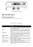
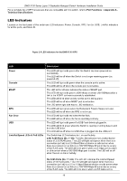
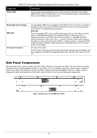
DMS-3130 Series Layer 3 Stackable Managed Switch Hardware Installation Guide For a complete list of SFP transceivers that are compatible with this switch, refer to Port Functions in Appendix A Technical Specifications. LED Indicators Located on the front panel of this switch are LED indicators: Power, Console, RPS, Fan Err, USB, Link/Act indicators for all the ports, and Stack ID. Figure 2-6 LED indicators for the DMS-3130-30PS LED Power Console MGMT RPS Fan Error USB Link/Act/Speed LEDs & PoE LEDs Description This LED will light solid green after the Switch has been powered on successfully. This LED will be off when the Switch is no longer receiving power (i.e. powered off). This LED will light solid green when the console port is active. This LED will be off when the console port is not active. The LED at the left side indicates the status of MGMT port. This LED will light solid green (1000 Mbps) or amber (10/100Mbps) after a link to the MGMT port was successfully established. This LED will blink when activity on this port is taking place. This LED will be off when MGMT port is not active. The LED at the right side has no LED notification. This LED will light green when the Redundant Powers Supply is in use. This LED will be off when the RPS is not in use. This LED will light solid red when the fan fails. This LED will be off when the fan is operating normally. This LED will light solid green if a USB flash drive is plugged in. This LED will blink green when the Switch is reading or writing data to and from the USB drive. This LED will be off when no USB drive is plugged into the USB port. The Switch has LED indicators for Link and Activity. 2.5G RJ45 Ports (No. 1~16): The left LED indicates the Link/Act/Speed status of 2.5G RJ45 ports. This LED will light solid green when there is a connection (or link) to a 2.5 Gbps Ethernet device or solid amber when there is a connection (or link) to a 100/1000 Mbps Ethernet device on any of the RJ45 ports. The LED will blink green when a 2.5 Gbps port is active or blink amber when a 100/1000 Mbps port is active. The LED will be off when there is no link or activity. 5G RJ45 Ports (No. 17~24): The left LED indicates the Link/Act/Speed status of 5G RJ45 ports. This LED will light solid green when there is a connection (or link) to a 2.5 or 5 Gbps Ethernet device or solid amber when there is a connection (or link) to a 100/1000 Mbps Ethernet device on any of the RJ45 ports. The LED will blink green when a 2.5/5 Gbps port is 18
-
 1
1 -
2
-
3
-
4
-
5
-
6
-
7
-
8
-
9
-
10
-
11
-
12
-
 13
13 -
 14
14 -
 15
15 -
 16
16 -
 17
17 -
 18
18 -
 19
19 -
 20
20 -
 21
21 -
 22
22 -
 23
23 -
24
-
25
-
26
-
27
-
28
-
29
-
30
-
31
-
32
-
33
-
34
-
35
-
36
-
37
-
38
-
39
-
40
-
41
-
42
-
43
-
44
-
45
-
46
-
47
-
48
-
49
-
50
-
51
-
52
 |
 |
