D-Link DMS-3130-30TS Product Manual - Page 21
Installation, Installation Guidelines, Installing the Switch without a Rack
 |
View all D-Link DMS-3130-30TS manuals
Add to My Manuals
Save this manual to your list of manuals |
Page 21 highlights
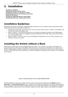
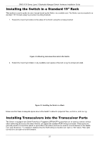
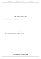
DMS-3130 Series Layer 3 Stackable Managed Switch Hardware Installation Guide 3. Installation Installation Guidelines Installing the Switch without a Rack Installing the Switch in a Standard 19" Rack Installing Transceivers into the Transceiver Ports Power On (AC Power) Installing the Redundant Power Supply (RPS) Installing the RPS into a Rack-mount Chassis Installation Guidelines This section will discuss the hardware installation guidelines that the user must follow in order to properly and safely install this switch into the appropriate environment. • Visually inspect the power cord and see that it is fully secured to both the power connector, on the Switch, and the electrical outlet that supplies power. • Install the Switch in a cool and dry place within the acceptable operating temperature and humidity ranges. For more information about the acceptable operating temperature and humidity ranges, refer to the Physical and Environmental section. • Install the Switch in a site free from strong electromagnetic field generators such as motors, vibration, dust, and direct exposure to sunlight. Installing the Switch without a Rack This section is used to guide the user through installing the Switch in an area other than a switch rack. Attach the included rubber feet to the bottom of the Switch. Take note that there should be marked blocks on the bottom of the Switch to indicate where to attach the rubber feet. These markings are usually found in each corner on the bottom of the device. The rubber feet cushion the Switch, protecting the casing from scratches and preventing it from scratching other surfaces. Figure 3-1 Attaching rubber feet to the Switch DMS-3130-30TS Install the Switch on a sturdy, level surface that can support the weight of the Switch (see the Weight section in Appendix A - Technical Specifications.). Do not place any heavy objects on the Switch. The power outlet should be within 1.82 meters (6 feet) of the Switch. Make sure that there is proper heat dissipation from and adequate ventilation around the Switch. Leave at least 10 cm (4 inches) of space at the front, sides, and rear of the Switch for ventilation. 21
-
 1
1 -
2
-
3
-
4
-
5
-
6
-
7
-
8
-
9
-
10
-
11
-
12
-
13
-
14
-
15
-
 16
16 -
 17
17 -
 18
18 -
 19
19 -
 20
20 -
 21
21 -
 22
22 -
 23
23 -
 24
24 -
 25
25 -
 26
26 -
27
-
28
-
29
-
30
-
31
-
32
-
33
-
34
-
35
-
36
-
37
-
38
-
39
-
40
-
41
-
42
-
43
-
44
-
45
-
46
-
47
-
48
-
49
-
50
-
51
-
52
 |
 |