D-Link DMS-3130-30TS Product Manual - Page 50
Redundant Power Supply (RPS) Cable, RPS Cable - 14 PIN Assignments
 |
View all D-Link DMS-3130-30TS manuals
Add to My Manuals
Save this manual to your list of manuals |
Page 50 highlights
DMS-3130 Series Layer 3 Stackable Managed Switch Hardware Installation Guide Redundant Power Supply (RPS) Cable When connecting the Switch to an external Redundant Power Supply, an RPS cable is necessary. Please review this product for matching cable pins. The following diagram and table show the standard RPS connector and its pin assignments. Figure B-3 RPS Cable for DPS-500A (14-pin Power Cable) RPS Cable - 14 PIN Assignments: Pin 1 2 3 4 5 6 7 8 9 10 11 12 13 14 Device Not Connected GND GND GND GND +12V +12V +12V Not Connected Not Connected RPS_Present RPS_Power Good Not Connected +12V DPS-500A GND N/C +12V +12V +12V +12V GND N/C N/C RPS Power N/C N/C PWR-Good GND 50
-
 1
1 -
2
-
3
-
4
-
5
-
6
-
7
-
8
-
9
-
10
-
11
-
12
-
13
-
14
-
15
-
16
-
17
-
18
-
19
-
20
-
21
-
22
-
23
-
24
-
25
-
26
-
27
-
28
-
29
-
30
-
31
-
32
-
33
-
34
-
35
-
36
-
37
-
38
-
39
-
40
-
41
-
42
-
43
-
44
-
 45
45 -
 46
46 -
 47
47 -
 48
48 -
 49
49 -
 50
50 -
 51
51 -
 52
52
 |
 |

DMS-3130 Series Layer 3 Stackable Managed Switch Hardware Installation Guide
50
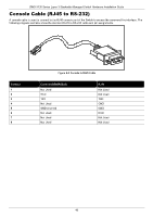
Redundant Power Supply (RPS) Cable
When connecting the Switch to an external Redundant Power Supply, an RPS cable is necessary. Please review this
product for matching cable pins. The following diagram and table show the standard RPS connector and its pin
assignments.
Figure B-3 RPS Cable for DPS-500A (14-pin Power Cable)
RPS Cable – 14 PIN Assignments:
Pin
Device
DPS-500A
1
Not Connected
GND
2
GND
N/C
3
GND
+12V
4
GND
+12V
5
GND
+12V
6
+12V
+12V
7
+12V
GND
8
+12V
N/C
9
Not Connected
N/C
10
Not Connected
RPS Power
11
RPS_Present
N/C
12
RPS_Power Good
N/C
13
Not Connected
PWR-Good
14
+12V
GND