D-Link DMS-3130-30TS Product Manual - Page 20
Side Panel Components, Switch GND, Redundant Power Supply, RPS LED, AC Power Connector
 |
View all D-Link DMS-3130-30TS manuals
Add to My Manuals
Save this manual to your list of manuals |
Page 20 highlights
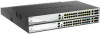
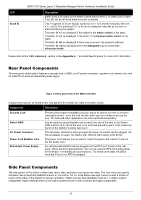
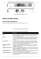
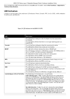
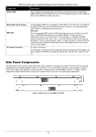
DMS-3130 Series Layer 3 Stackable Managed Switch Hardware Installation Guide Component Switch GND Description Use an electrical grounding wire and connect one end of the wire to the Switch GND and the other end of the wire to an electrical grounding point most commonly found on the Switch mounting rack itself. Redundant Power Supply RPS LED AC Power Connector A hot-pluggable RPS can be plugged into the RPS port found on the rear panel of the Switch. When one of the two RPS units fails, the other one will supply power to the Switch immediately and automatically. RPS LED: The hot-pluggable RPS carries a LED which stays green or red. When it is solid green, it shows that the power unit is working. When it is flashing green, it indicates the power is at 12Vsb. When it is solid amber, it indicates that RPS stops working due to lost power input. It can also indicate critical events such as fan failure or over-current protection. When it is flashing amber, it shows that RPS is still working but requires maintenance due to high temperature or high current or fan in slow speed. AC Power Connector: The AC power cord with a three-pronged AC power connector can be plugged into this receptacle of the RPS to supply the Switch with 100-240 VAC power at 47-63 Hz. Side Panel Components The side panels of this switch contain heat vents, fans, and rack-mounting screw holes. The heat vents are used to dissipate internal heat and facilitate internal air circulation. Do not block these openings. Leave at least 4 inches of space at the sides of the Switch for proper ventilation. Without proper heat dissipation and air circulation, system components might overheat which could lead to system failure or even severely damaged components. Figure 2-8 Side panels of the DMS-3130-30PS 20
-
 1
1 -
2
-
3
-
4
-
5
-
6
-
7
-
8
-
9
-
10
-
11
-
12
-
13
-
14
-
 15
15 -
 16
16 -
 17
17 -
 18
18 -
 19
19 -
 20
20 -
 21
21 -
 22
22 -
 23
23 -
 24
24 -
 25
25 -
26
-
27
-
28
-
29
-
30
-
31
-
32
-
33
-
34
-
35
-
36
-
37
-
38
-
39
-
40
-
41
-
42
-
43
-
44
-
45
-
46
-
47
-
48
-
49
-
50
-
51
-
52
 |
 |
