D-Link DMS-3130-30TS Product Manual - Page 19
Rear Panel Components, The triangle LED indicates the Link/Act/Speed
 |
View all D-Link DMS-3130-30TS manuals
Add to My Manuals
Save this manual to your list of manuals |
Page 19 highlights
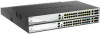
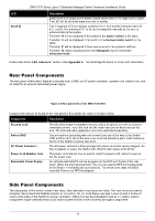
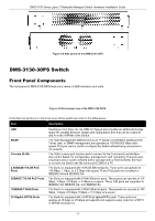
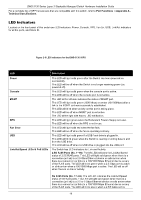
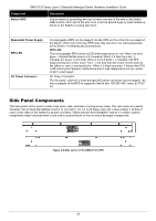
LED Stack ID DMS-3130 Series Layer 3 Stackable Managed Switch Hardware Installation Guide Description active or blink amber when a 100/1000 Mbps port is active. The LED will be off when there is no link or activity. PoE LED (No. 1~24): The right LEDs of the above ports indicate power supply status. This LED will light solid green when there is a PoE device connected to the port and is receiving power from the port. This LED will light amber to indicate an error state in power supply. The LED is off when there is no PD connected to the port. 10G RJ45 Ports (No. 25~26): The left LED will light solid green when there is a connection (or link) to a 2.5/5/10 Gbps Ethernet device; the right LED will light solid amber when there is a connection (or link) to a 100/1000 Mbps Ethernet device on any of the RJ45 ports. The left LED will blink green when a 2.5/5/10 Gbps port is active; the right LED will blink amber when a 100/1000 Mbps port is active. The LED will be off when there is no link or activity. SFP28 Ports (N0. 27~30): The triangle LED indicates the Link/Act/Speed status of 25G SFP28 ports. This LED will light solid green when there is a connection (or link) to a 25 Gbps Ethernet device or solid amber when there is a connection (or link) to a 10 Gbps Ethernet device on any of the SFP28 ports. The LED will blink green when a 25 Gbps port is active or blink amber when a 10 Gbps port is active. The LED will be off when there is no link or activity. This 7-segment LED can display numbers from 1 to 9 and the following letters H, h, E, and G. The stacking ID (1 to 9) can be assigned manually by the user or automatically by the system. The letter 'H' will be displayed if this switch is the master switch in the stack. The letter 'h' will be displayed if this switch is the backup master switch in the stack. The letter 'E' will be displayed if there was an error in the system's self-test. The letter 'G' will be displayed when the Safeguard engine entered the exhausted mode. Please refer to the "LED Indicators" section in the Appendix A - Technical Specifications for more LED information. Rear Panel Components The rear panel of this switch features a GND and two hot-pluggable power supplies. Figure 2-7 Rear panel view of the DMS-3130-30PS Components that can be found on the rear panel of this switch are listed in the table below. 19
-
 1
1 -
2
-
3
-
4
-
5
-
6
-
7
-
8
-
9
-
10
-
11
-
12
-
13
-
 14
14 -
 15
15 -
 16
16 -
 17
17 -
 18
18 -
 19
19 -
 20
20 -
 21
21 -
 22
22 -
 23
23 -
 24
24 -
25
-
26
-
27
-
28
-
29
-
30
-
31
-
32
-
33
-
34
-
35
-
36
-
37
-
38
-
39
-
40
-
41
-
42
-
43
-
44
-
45
-
46
-
47
-
48
-
49
-
50
-
51
-
52
 |
 |
