D-Link DMS-3130-30TS Product Manual - Page 27
DPS-500A/DPS-500DC, CAUTION, Install the DPS-500A in the DPS-800
 |
View all D-Link DMS-3130-30TS manuals
Add to My Manuals
Save this manual to your list of manuals |
Page 27 highlights
DMS-3130 Series Layer 3 Stackable Managed Switch Hardware Installation Guide NOTE: This rack-mount chassis supports the following RPS units: DPS-500A/DPS-500DC. The following diagram illustrates how a DPS-500A is installed into a DPS-800. Figure 3-11 Install the DPS-500A in the DPS-800 The DPS-800 can be mounted into a standard 19" rack, as shown below. Figure 3-12 Install the DPS-800 in an Equipment Rack CAUTION: This equipment is only to be connected to PoE networks without routing to outside plant. 27
-
 1
1 -
2
-
3
-
4
-
5
-
6
-
7
-
8
-
9
-
10
-
11
-
12
-
13
-
14
-
15
-
16
-
17
-
18
-
19
-
20
-
21
-
 22
22 -
 23
23 -
 24
24 -
 25
25 -
 26
26 -
 27
27 -
 28
28 -
 29
29 -
 30
30 -
 31
31 -
 32
32 -
33
-
34
-
35
-
36
-
37
-
38
-
39
-
40
-
41
-
42
-
43
-
44
-
45
-
46
-
47
-
48
-
49
-
50
-
51
-
52
 |
 |

DMS-3130 Series Layer 3 Stackable Managed Switch Hardware Installation Guide
27
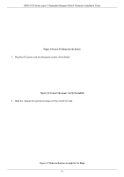
NOTE:
This rack-mount chassis supports the following RPS units:
DPS-500A/DPS-500DC
.
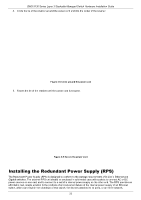
The following diagram illustrates how a DPS-500A is installed into a DPS-800.
Figure 3–11 Install the DPS-500A in the DPS-800
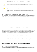
The DPS-800 can be mounted into a standard 19" rack, as shown below.
Figure 3–12 Install the DPS-800 in an Equipment Rack
CAUTION:
This equipment is only to be connected to PoE networks without routing to outside plant.