Dell Alienware 17 R2 Service Manual
Dell Alienware 17 R2 Manual
 |
View all Dell Alienware 17 R2 manuals
Add to My Manuals
Save this manual to your list of manuals |
Dell Alienware 17 R2 manual content summary:
- Dell Alienware 17 R2 | Service Manual - Page 1
Alienware 17 R2 Service Manual Computer Model: Alienware 17 R2 Regulatory Model: P43F Regulatory Type: P43F001 - Dell Alienware 17 R2 | Service Manual - Page 2
potential damage to hardware or loss of data and tells you how to avoid the problem. WARNING: A WARNING indicates a potential for property damage, personal injury, or death. Copyright © 2015 Dell Inc. All rights reserved. This product is protected by U.S. and international copyright and intellectual - Dell Alienware 17 R2 | Service Manual - Page 3
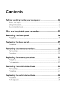
Before working inside your computer 12 Before you begin 12 Safety instructions 12 Recommended tools 13 After working inside your computer 15 Removing the base panel 16 Procedure...16 Replacing the base panel 19 Procedure...19 Removing the memory modules 20 Prerequisites...20 Procedure...20 - Dell Alienware 17 R2 | Service Manual - Page 4
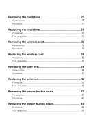
Removing the hard drive 27 Prerequisites...27 Procedure...27 Replacing the hard drive 30 Procedure...30 Post-requisites 30 Removing the wireless card 31 Prerequisites...31 Procedure...31 Replacing the wireless card 33 Procedure...33 Post-requisites 33 Removing the palm rest 34 Prerequisites - Dell Alienware 17 R2 | Service Manual - Page 5
status-light board 47 Procedure...47 Post-requisites 47 Removing the keyboard 48 Prerequisites...48 Procedure...48 Replacing the keyboard 52 Procedure...52 Post-requisites 52 Removing the touch pad 53 Prerequisites...53 Procedure...54 Replacing the touch pad 56 Procedure...56 Post-requisites - Dell Alienware 17 R2 | Service Manual - Page 6
...62 Procedure...62 Replacing the battery 65 Procedure...65 Post-requisites 65 Removing the I/O board 66 Prerequisites...66 Procedure...66 Replacing the I/O board 68 Procedure...68 Post-requisites 68 Removing the speakers 69 Prerequisites...69 Procedure...69 Replacing the speakers 72 - Dell Alienware 17 R2 | Service Manual - Page 7
83 Procedure...83 Post-requisites 83 Removing the heat sink 84 Prerequisites...84 Procedure...84 Replacing the heat sink 86 Procedure...86 Post-requisites 86 Removing the coin-cell battery 87 Prerequisites...87 Procedure...87 Replacing the coin-cell battery 89 Procedure...89 Post-requisites - Dell Alienware 17 R2 | Service Manual - Page 8
fan 90 Prerequisites...90 Procedure...90 Replacing the video-card fan 92 Procedure...92 Post-requisites 92 Removing the power-adapter port 93 Prerequisites...93 Procedure...93 Replacing the power-adapter port 95 Procedure...95 Post-requisites 95 Removing the subwoofer 96 Prerequisites...96 - Dell Alienware 17 R2 | Service Manual - Page 9
hinges 112 Procedure...112 Post-requisites 112 Removing the computer base 113 Prerequisites 113 Procedure...113 Replacing the computer base 115 Procedure...115 Post-requisites 115 Removing the logo board 116 Prerequisites 116 Procedure...117 Replacing the logo board 119 Procedure...119 Post - Dell Alienware 17 R2 | Service Manual - Page 10
-panel AlienFX LEDs 126 Procedure...126 Post-requisites 126 Removing the Alienware AlienHead LED board 127 Prerequisites 127 Procedure...127 Replacing the Alienware AlienHead LED board 130 Procedure...130 Post-requisites 130 Removing the display back-cover 131 Prerequisites 131 Procedure - Dell Alienware 17 R2 | Service Manual - Page 11
135 Overview...135 Entering BIOS setup program 135 BIOS setup program options 135 Boot sequence 141 Boot options 141 Changing boot sequence for the current boot 142 Changing boot sequence for future boots 142 Flashing the BIOS 144 Getting help and contacting Alienware 145 Self-help resources - Dell Alienware 17 R2 | Service Manual - Page 12
8.1: On the Start screen, click or tap the power icon → Shut down. - Windows 7: Click or tap Start → Shut down . NOTE: If you are using a different operating system, see the documentation of your operating system for shut-down instructions. 3 Disconnect your computer and all attached devices from - Dell Alienware 17 R2 | Service Manual - Page 13
pins and contacts. CAUTION: You should only perform troubleshooting and repairs as authorized or directed by the Dell technical assistance team. Damage due to servicing that is not authorized by Dell is not covered by your warranty. See the safety instructions that shipped with the product or at - Dell Alienware 17 R2 | Service Manual - Page 14
• Philips screwdriver • Plastic scribe 14 - Dell Alienware 17 R2 | Service Manual - Page 15
screws remain inside your computer. 2 Connect any external devices, peripherals, and cables you removed before working on your computer. 3 Replace any media cards, discs, and any other part(s) that you removed before working on your computer. 4 Connect your computer and all attached devices to their - Dell Alienware 17 R2 | Service Manual - Page 16
Before Working Inside Your Computer. After working inside your computer, follow the instructions in After Working Inside Your Computer. For more safety best practices, see the Regulatory Compliance home page at dell.com/regulatory_compliance. Procedure 1 Close the display and turn the computer over - Dell Alienware 17 R2 | Service Manual - Page 17
4 Slide and remove the base panel from the computer base. 1 computer base 3 base panel 2 captive screws (2) 4 plastic scribe 17 - Dell Alienware 17 R2 | Service Manual - Page 18
5 Disconnect the battery cable from the system board. 1 battery cable 6 Turn the computer over. 7 Press and hold the power button for 5 seconds to ground the system board. 18 - Dell Alienware 17 R2 | Service Manual - Page 19
Your Computer. After working inside your computer, follow the instructions in After Working Inside Your Computer. For more safety best practices, see the Regulatory Compliance home page at dell.com/regulatory_compliance. Procedure 1 Connect the battery cable to the system board. 2 Slide the tabs on - Dell Alienware 17 R2 | Service Manual - Page 20
Computer. After working inside your computer, follow the instructions in After Working Inside Your Computer. For more safety best practices, see the Regulatory Compliance home page at dell.com/regulatory_compliance. Prerequisites Remove the base panel. Procedure 1 Using your fingertips, carefully - Dell Alienware 17 R2 | Service Manual - Page 21
2 Slide and remove the memory module from the memory-module slot. 1 securing clips (2) 3 memory-module slot 2 memory modules (2) 21 - Dell Alienware 17 R2 | Service Manual - Page 22
Before Working Inside Your Computer. After working inside your computer, follow the instructions in After Working Inside Your Computer. For more safety best practices, see the Regulatory Compliance home page at dell.com/regulatory_compliance. Procedure 1 Align the notch on the memory module with the - Dell Alienware 17 R2 | Service Manual - Page 23
into the slot at an angle and press the memory module down until it clicks into place. NOTE: If you do not hear the click, remove the memory module and reinstall it. 1 securing clips (2) 3 memory-module slot 5 tab Post-requisites Replace the base panel. 2 memory module 4 notch 23 - Dell Alienware 17 R2 | Service Manual - Page 24
the instructions in After Working Inside Your Computer. For more safety best practices, see the Regulatory Compliance home page at dell.com/regulatory_compliance. CAUTION: Solid-state drives are fragile. Exercise care when handling the hard drive. CAUTION: To avoid data loss, do not remove the - Dell Alienware 17 R2 | Service Manual - Page 25
2 Slide and remove the solid-state drive from the solid-state drive slot. 1 solid-state drive slot 3 screw 2 solid-state drive 25 - Dell Alienware 17 R2 | Service Manual - Page 26
best practices, see the Regulatory Compliance home page at dell.com/regulatory_compliance. CAUTION: Solid-state drives are fragile. Exercise care when handling the hard drive. Procedure 1 Slide the solid-state drive into the solid-state drive slot. 2 Replace the screw that secures the solid-state - Dell Alienware 17 R2 | Service Manual - Page 27
the instructions in After Working Inside Your Computer. For more safety best practices, see the Regulatory Compliance home page at dell.com/regulatory_compliance. CAUTION: Hard drives are fragile. Exercise care when handling the hard drive. CAUTION: To avoid data loss, do not remove the hard drive - Dell Alienware 17 R2 | Service Manual - Page 28
the hard-drive assembly off the computer base. 1 pull tab 3 screws (4) 2 hard-drive cable 4 hard-drive assembly 5 Remove the screws that secure the hard-drive bracket to the hard drive. 6 Lift the hard-drive bracket off the hard-drive assembly. 1 hard drive 3 screws (4) 28 2 hard-drive bracket - Dell Alienware 17 R2 | Service Manual - Page 29
7 Disconnect the interposer from the hard drive. 1 interposer 2 hard drive 29 - Dell Alienware 17 R2 | Service Manual - Page 30
that secure the hard-drive bracket to the hard-drive assembly. 4 Align the screw holes on the hard-drive assembly with the screw holes on the computer base. 5 Replace the screws that secure the hard-drive assembly to the computer base. 6 Route the hard-drive cable through the routing guides on the - Dell Alienware 17 R2 | Service Manual - Page 31
Compliance home page at dell.com/regulatory_compliance. Prerequisites Remove the base panel. Procedure 1 Remove the screw that secures the wireless-card bracket and the wireless card to the system board. 2 Lift the wireless-card bracket off the wireless card. 3 Disconnect the antenna cables - Dell Alienware 17 R2 | Service Manual - Page 32
4 Lift and slide the wireless card from the wireless-card slot. 1 antenna cables 3 screw 5 wireless-card slot 2 wireless-card bracket 4 wireless card 32 - Dell Alienware 17 R2 | Service Manual - Page 33
scheme for the wireless card supported by your computer. Connectors on the wireless card Antenna-cable color Main (white triangle) White Auxiliary (black triangle) Black 4 Align the screw hole on the wireless-card bracket with the screw hole on the wireless card. 5 Replace the screw that - Dell Alienware 17 R2 | Service Manual - Page 34
the steps in Before Working Inside Your Computer. After working inside your computer, follow the instructions in After Working Inside Your Computer. For more safety best practices, see the Regulatory Compliance home page at dell.com/regulatory_compliance. Prerequisites Remove the base panel. 34 - Dell Alienware 17 R2 | Service Manual - Page 35
Procedure 1 Lift the latches and disconnect the keyboard cable, keyboard-backlight cable, macro-keys cable and macro-keys backlight cable from the system board. 1 keyboard-backlight cable 3 macro-keys cable 2 keyboard cable 4 macro-keys backlight cable 35 - Dell Alienware 17 R2 | Service Manual - Page 36
2 Remove the screws that secure the palm-rest assembly to the computer base. 1 computer base 2 screws (16) 36 - Dell Alienware 17 R2 | Service Manual - Page 37
3 Lift the computer base slightly and push the palm-rest assembly through the slot on the computer base to release the tabs on the palm-rest assembly. 1 slot 2 palm-rest assembly 4 Turn the computer over and open the display as far as possible. 5 Using a plastic - Dell Alienware 17 R2 | Service Manual - Page 38
6 Gently lift the palm-rest assembly and turn it over. 1 plastic scribe 2 palm-rest assembly 7 Peel the tape that secures the power-button board cable to the system board. 8 Disconnect the power-button board cable from the system board. 38 - Dell Alienware 17 R2 | Service Manual - Page 39
9 Lift the palm-rest assembly off the computer base. 1 palm-rest assembly 3 latch 10 Remove the power-button board. 11 Remove the status-light board. 12 Remove the keyboard. 2 power-button board cable 39 - Dell Alienware 17 R2 | Service Manual - Page 40
13 Remove the touch pad. 1 palm rest 40 - Dell Alienware 17 R2 | Service Manual - Page 41
, follow the instructions in After Working Inside Your Computer. For more safety best practices, see the Regulatory Compliance home page at dell.com/regulatory_compliance. Procedure 1 Replace the touch pad. 2 Replace the keyboard. 3 Replace the status-light board. 4 Replace the power-button board - Dell Alienware 17 R2 | Service Manual - Page 42
Your Computer. After working inside your computer, follow the instructions in After Working Inside Your Computer. For more safety best practices, see the Regulatory Compliance home page at dell.com/regulatory_compliance. Prerequisites 1 Remove the base panel. 2 Follow the procedure from step 1 to - Dell Alienware 17 R2 | Service Manual - Page 43
4 Lift the power-button board off the palm-rest assembly. 1 power-button board cable 3 touch-pad cable 5 screws (2) 2 latches (2) 4 status-light cable 6 power-button board 43 - Dell Alienware 17 R2 | Service Manual - Page 44
, follow the instructions in After Working Inside Your Computer. For more safety best practices, see the Regulatory Compliance home page at dell.com/regulatory_compliance. Procedure 1 Align the screw holes on the power-button board with the screw holes on the palm-rest assembly. 2 Replace the screws - Dell Alienware 17 R2 | Service Manual - Page 45
Your Computer. After working inside your computer, follow the instructions in After Working Inside Your Computer. For more safety best practices, see the Regulatory Compliance home page at dell.com/regulatory_compliance. Prerequisites 1 Remove the base panel. 2 Follow the procedure from step 1 to - Dell Alienware 17 R2 | Service Manual - Page 46
3 Lift the status-light board off the palm-rest assembly. 1 screws (2) 3 status-light board cable 2 latch 4 status-light board 46 - Dell Alienware 17 R2 | Service Manual - Page 47
, follow the instructions in After Working Inside Your Computer. For more safety best practices, see the Regulatory Compliance home page at dell.com/regulatory_compliance. Procedure 1 Align the screw holes on the status-light board with the screw holes on the palm-rest assembly. 2 Replace the screws - Dell Alienware 17 R2 | Service Manual - Page 48
Your Computer. After working inside your computer, follow the instructions in After Working Inside Your Computer. For more safety best practices, see the Regulatory Compliance home page at dell.com/regulatory_compliance. Prerequisites 1 Remove the base panel. 2 Follow the procedure from step 1 to - Dell Alienware 17 R2 | Service Manual - Page 49
cable routing and peel off the cables from the keyboard bracket. 1 latches (2) 3 status-light cable 2 touch-pad cable 3 Remove the screws that secure the keyboard bracket to the palm-rest assembly. 4 Slide the keyboard cable, keyboard-backlight cable, macro-keys cable and macro-keys backlight - Dell Alienware 17 R2 | Service Manual - Page 50
5 Lift the keyboard bracket off the palm-rest assembly. 1 screws (14) 3 palm-rest assembly 2 keyboard bracket 6 Remove the screws that secure the keyboard to the palm-rest assembly. 7 Release the tabs that secure the keyboard to the palm-rest assembly. 50 - Dell Alienware 17 R2 | Service Manual - Page 51
8 Slide and lift the keyboard along with the cables off the palm-rest assembly. 1 tabs (5) 3 screws (2) 2 keyboard 51 - Dell Alienware 17 R2 | Service Manual - Page 52
Regulatory Compliance home page at dell.com/regulatory_compliance. Procedure 1 Slide the keyboard under the tabs on the palm-rest assembly. 2 Align the screw holes on the keyboard with the screw holes on the palm- rest assembly. 3 Replace the screws that secure the keyboard to the palm-rest assembly - Dell Alienware 17 R2 | Service Manual - Page 53
Your Computer. After working inside your computer, follow the instructions in After Working Inside Your Computer. For more safety best practices, see the Regulatory Compliance home page at dell.com/regulatory_compliance. Prerequisites 1 Remove the base panel. 2 Follow the procedure from step 1 to - Dell Alienware 17 R2 | Service Manual - Page 54
Procedure 1 Lift the latches and disconnect the touch-pad cable and touch-pad button cable from the touch pad. 1 touch-pad cable 3 touch-pad button cable 2 latches (2) 2 Remove the screws that secure the touch-pad button bracket to the palm-rest assembly. 54 - Dell Alienware 17 R2 | Service Manual - Page 55
3 Lift the touch-pad button bracket off the palm-rest assembly. 1 touch-pad button bracket 2 screws (5) 4 Lift the touch pad off the palm-rest assembly. 1 touch pad 55 - Dell Alienware 17 R2 | Service Manual - Page 56
the instructions in After Working Inside Your Computer. For more safety best practices, see the Regulatory Compliance home page at dell. touch-pad button bracket with the screw holes on the palm-rest assembly. 4 Replace the screws that secure the touch-pad button bracket to the palm-rest assembly. - Dell Alienware 17 R2 | Service Manual - Page 57
For more safety best practices, see the Regulatory Compliance home page at dell.com/regulatory_compliance. Prerequisites 1 Remove the base panel. 2 Remove the wireless card. 3 Follow the procedure from step 1 to step 9 in "Removing the palm rest". Procedure 1 Close the display and turn the computer - Dell Alienware 17 R2 | Service Manual - Page 58
and open the display. 6 Peel off the adhesive tape that secures the antenna cables to the system board. 7 Carefully remove the antenna cables up from the computer base and remove it from the routing guides on the display hinges. 8 Lift the latch and disconnect the display cable from the system board - Dell Alienware 17 R2 | Service Manual - Page 59
10 Disconnect the logo-board cable from the system board and remove it from the routing guide on the display hinge. 1 display cable 3 connector 5 antenna cables 2 latch 4 logo-board cable 6 tape 11 Remove the screws that secure the display assembly to the computer base. 59 - Dell Alienware 17 R2 | Service Manual - Page 60
12 Lift the display assembly off the computer base. 1 display assembly 3 computer base 2 screws (4) 4 display hinges (2) 60 - Dell Alienware 17 R2 | Service Manual - Page 61
instructions in After Working Inside Your Computer. For more safety best practices, see the Regulatory Compliance home page at dell.com/regulatory_compliance. Procedure 1 Align the screw holes on the display hinges with the screw holes on the computer base. 2 Replace the routing guide on the display - Dell Alienware 17 R2 | Service Manual - Page 62
Your Computer. After working inside your computer, follow the instructions in After Working Inside Your Computer. For more safety best practices, see the Regulatory Compliance home page at dell.com/regulatory_compliance. Prerequisites 1 Remove the base panel. 2 Follow the procedure from step 1 to - Dell Alienware 17 R2 | Service Manual - Page 63
3 Note the front AlienFX LED cable routing and peel off the cable from the battery. 1 system board 3 front AlienFX LED cable 2 speaker cable 4 Remove the battery cable from the slot on the computer base. 5 Remove the screws that secure the battery to the computer base. 63 - Dell Alienware 17 R2 | Service Manual - Page 64
6 Lift the battery off the computer base. 1 battery cable 3 screws (6) 2 battery 64 - Dell Alienware 17 R2 | Service Manual - Page 65
computer, follow the instructions in After Working Inside Your Computer. For more safety best practices, see the Regulatory Compliance home page at dell.com/regulatory_compliance. Procedure 1 Align the screw holes on the battery with the screw holes on the computer base. 2 Replace the screws that - Dell Alienware 17 R2 | Service Manual - Page 66
instructions in After Working Inside Your Computer. For more safety best practices, see the Regulatory Compliance home page at dell.com/regulatory_compliance. Prerequisites 1 Remove board. 3 Remove the screws that secure the I/O board to the computer base. 4 Gently tilt and lift to release the I/O - Dell Alienware 17 R2 | Service Manual - Page 67
5 Lift the I/O board off the computer base. 1 subwoofer cable 3 I/O-board cable 5 I/O board 2 latch 4 screws (2) 67 - Dell Alienware 17 R2 | Service Manual - Page 68
in Before Working Inside Your Computer. After working inside your computer, follow the instructions in After Working Inside Your Computer. For more safety best practices, see the Regulatory Compliance home page at dell.com/regulatory_compliance. Procedure 1 Align the ports on the I/O board with the - Dell Alienware 17 R2 | Service Manual - Page 69
Your Computer. After working inside your computer, follow the instructions in After Working Inside Your Computer. For more safety best practices, see the Regulatory Compliance home page at dell.com/regulatory_compliance. Prerequisites 1 Remove the base panel. 2 Follow the procedure from step 1 to - Dell Alienware 17 R2 | Service Manual - Page 70
2 Note the front AlienFX LED cable routing and peel off the cable from the battery. 1 connector 2 front AlienFX LED cable 3 Disconnect the speaker cable from the system board. 4 Remove the speaker cable from the routing guides on the battery and computer base. 70 - Dell Alienware 17 R2 | Service Manual - Page 71
5 Lift the speakers along with its cable off the computer base. 1 speaker cable 3 alignment posts (4) 5 speakers (2) 2 system board 4 computer base 6 routing guides 71 - Dell Alienware 17 R2 | Service Manual - Page 72
computer base and battery. 3 Route the front AlienFX LED cable through the routing guides on the battery. 4 Connect the speaker cable and front AlienFX LED cable to the system board. Post-requisites 1 Follow the procedure from step 5 to step 11 in "Replacing the palm rest". 2 Replace the base panel - Dell Alienware 17 R2 | Service Manual - Page 73
Your Computer. After working inside your computer, follow the instructions in After Working Inside Your Computer. For more safety best practices, see the Regulatory Compliance home page at dell.com/regulatory_compliance. Prerequisites 1 Remove the base panel. 2 Follow the procedure from step 1 to - Dell Alienware 17 R2 | Service Manual - Page 74
3 Lift the front AlienFX LED boards off the computer base. 1 front AlienFX LED boards (2) 3 screws (2) 2 front AlienFX LED board cables (2) 74 - Dell Alienware 17 R2 | Service Manual - Page 75
Working Inside Your Computer. After working inside your computer, follow the instructions in After Working Inside Your Computer. For more safety best practices, see the Regulatory Compliance home page at dell.com/regulatory_compliance. Procedure 1 Using the alignment posts on the computer base - Dell Alienware 17 R2 | Service Manual - Page 76
Your Computer. After working inside your computer, follow the instructions in After Working Inside Your Computer. For more safety best practices, see the Regulatory Compliance home page at dell.com/regulatory_compliance. Prerequisites 1 Remove the base panel. 2 Follow the procedure from step 1 to - Dell Alienware 17 R2 | Service Manual - Page 77
4 Remove the screws that secure the processor fan to the computer base. 5 Peel off the Mylar from the processor heat-sink and processor fan. 6 Slide and lift the processor fan off the computer base. 1 mylar 3 screws (2) 2 processor fan 77 - Dell Alienware 17 R2 | Service Manual - Page 78
instructions in After Working Inside Your Computer. For more safety best practices, see the Regulatory Compliance home page at dell base. 3 Adhere the Mylar on the processor fan and processor heat-sink. 4 Replace the screws that secure the processor fan to the computer base. 5 Close the display - Dell Alienware 17 R2 | Service Manual - Page 79
the Regulatory Compliance home page at dell.com/regulatory_compliance. NOTE: Your computer's Service Tag is stored in the system board. You must enter the Service Tag in the BIOS setup program after you replace the system board. NOTE: Replacing the system board removes any changes you have made to - Dell Alienware 17 R2 | Service Manual - Page 80
2 Disconnect the processor-fan cable, video-card fan cable, hard-drive cable and power-adapter port cable from the system board. 1 processor-fan cable 3 video-card fan cable 5 hard-drive cable 2 power-adapter port cable 4 system board 3 Turn the computer over. 4 Disconnect the speaker and front - Dell Alienware 17 R2 | Service Manual - Page 81
5 Lift the latch and disconnect the I/O-board cable from the system board. 1 I/O-board cable 3 system board 5 front AlienFX LED cable 2 latch 4 speaker cable 6 Remove the screws that secure the system board to the computer base. 81 - Dell Alienware 17 R2 | Service Manual - Page 82
7 Lift the system board off the computer base. 1 screws (6) 2 system board 82 - Dell Alienware 17 R2 | Service Manual - Page 83
the processor-fan cable, video-card fan cable, hard-drive cable, and power-adapter port cable to the system board. Post-requisites 1 Replace the display assembly. 2 Follow the procedure from step 5 to step 11 in "Replacing the palm rest". 3 Replace the wireless card. 4 Replace the base panel. 83 - Dell Alienware 17 R2 | Service Manual - Page 84
the instructions in After Working Inside Your Computer. For more safety best practices, see the Regulatory Compliance home page at dell. Remove the base panel. 2 Remove the wireless card. 3 Follow the procedure from step 1 to step 9 in "Removing the palm rest". 4 Remove the display assembly. 5 Remove - Dell Alienware 17 R2 | Service Manual - Page 85
2 Lift the heat sink off the system board. 1 system board 3 heat sink 2 captive screws (8) 85 - Dell Alienware 17 R2 | Service Manual - Page 86
screws that secure the heat sink to the system board. 3 Turn the system board over. Post-requisites 1 Replace the system board. 2 Replace the display assembly. 3 Follow the procedure from step 5 to step 11 in "Replacing the palm rest". 4 Replace the wireless card. 5 Replace the base panel. 86 - Dell Alienware 17 R2 | Service Manual - Page 87
home page at dell.com/regulatory_compliance. CAUTION: Removing the coin-cell battery resets the BIOS settings to default. It is recommended that you note the BIOS settings before removing the coin-cell battery. Prerequisites 1 Remove the base panel. 2 Remove the wireless card. 3 Follow the procedure - Dell Alienware 17 R2 | Service Manual - Page 88
2 Peel the coin-cell battery off the system board. 1 coin-cell battery cable 2 coin-cell battery 88 - Dell Alienware 17 R2 | Service Manual - Page 89
system board. 2 Connect the coin-cell battery cable to the connector on the system board. Post-requisites 1 Replace the system board. 2 Replace the display assembly. 3 Follow the procedure from step 5 to step 11 in "Replacing the palm rest". 4 Replace the wireless card. 5 Replace the base panel. 89 - Dell Alienware 17 R2 | Service Manual - Page 90
Compliance home page at dell.com/regulatory_compliance. Prerequisites 1 Remove the base panel. 2 Remove the wireless card. 3 Follow the procedure from step 1 to step 9 in "Removing the palm rest". 4 Remove the display assembly. 5 Remove the system board. Procedure 1 Remove the screws that secure - Dell Alienware 17 R2 | Service Manual - Page 91
2 Lift the video-card fan off the computer base. 1 screws (2) 2 video-card fan 91 - Dell Alienware 17 R2 | Service Manual - Page 92
home page at dell.com/regulatory_compliance. Procedure 1 Align the screw holes on the video-card fan with the screw holes on the computer base. 2 Replace the screws that secure the video-card fan to the computer base. Post-requisites 1 Replace the system board. 2 Replace the display assembly - Dell Alienware 17 R2 | Service Manual - Page 93
page at dell.com/regulatory_compliance. Prerequisites 1 Remove the base panel. 2 Remove the wireless card. 3 Follow the procedure from step 1 to step 9 in "Removing the palm rest". 4 Remove the display assembly. 5 Remove the system board. Procedure 1 Remove the screws that secure the power-adapter - Dell Alienware 17 R2 | Service Manual - Page 94
4 Lift the power-adapter port along with its cable off the computer base. 1 screws (2) 3 power-adapter port 2 power-adapter port bracket 94 - Dell Alienware 17 R2 | Service Manual - Page 95
port. 4 Route the power-adapter port cable through the routing guides on the computer base. Post-requisites 1 Replace the system board. 2 Replace the display assembly. 3 Follow the procedure from step 5 to step 11 in "Replacing the palm rest". 4 Replace the wireless card. 5 Replace the base panel - Dell Alienware 17 R2 | Service Manual - Page 96
home page at dell.com/regulatory_compliance. Prerequisites 1 Remove the base panel. 2 Remove the wireless card. 3 Follow the procedure from step 1 to step 9 in "Removing the palm rest". 4 Remove the display assembly. 5 Remove the system board. 6 Remove the I/O board. Procedure 1 Remove the screws - Dell Alienware 17 R2 | Service Manual - Page 97
2 Lift the subwoofer off the computer base. 1 screws (2) 2 subwoofer 97 - Dell Alienware 17 R2 | Service Manual - Page 98
computer, follow the instructions in After Working Inside Your Computer. For more safety best practices, see the Regulatory Compliance home page at dell.com/regulatory_compliance. Procedure 1 Align the screw holes on the subwoofer with the screw holes on the computer base. 2 Replace the screws that - Dell Alienware 17 R2 | Service Manual - Page 99
practices, see the Regulatory Compliance home page at dell.com/regulatory_compliance. Prerequisites NOTE: This chapter is applicable only if you have purchased a laptop with non-touchscreen display. 1 Remove the base panel. 2 Remove the wireless card. 3 Follow the procedure from step 1 to step 9 in - Dell Alienware 17 R2 | Service Manual - Page 100
2 Carefully lift the display bezel and turn it over. 1 display bezel 3 Lift the latches and disconnect the display-board cables from the logo board. 100 - Dell Alienware 17 R2 | Service Manual - Page 101
4 Lift the display-bezel assembly away from the display assembly. 1 display bezel 3 latches (3) 2 logo board 4 display-board cables (3) 5 Peel off the tape that secures the logo-board cable to the logo board and disconnect the logo-board cable. 101 - Dell Alienware 17 R2 | Service Manual - Page 102
6 Peel off the logo board from the display bezel. 1 display bezel 3 plastic scribe 5 tape 2 logo board 4 logo-board cable 102 - Dell Alienware 17 R2 | Service Manual - Page 103
7 After performing the above steps, we are left with the display bezel. 1 display bezel 103 - Dell Alienware 17 R2 | Service Manual - Page 104
inside your computer, follow the instructions in After Working Inside Your Computer. For more safety best practices, see the Regulatory Compliance home page at dell.com/regulatory_compliance. Procedure NOTE: This chapter is applicable only if you have purchased a laptop with non-touchscreen display - Dell Alienware 17 R2 | Service Manual - Page 105
practices, see the Regulatory Compliance home page at dell.com/regulatory_compliance. Prerequisites NOTE: This chapter is applicable only if you have purchased a laptop with non-touchscreen display. 1 Remove the base panel. 2 Remove the wireless card. 3 Follow the procedure from step 1 to step 9 in - Dell Alienware 17 R2 | Service Manual - Page 106
2 Gently lift the display panel and turn it over. 1 screws (4) 3 display back-cover 2 display panel 3 Lift the latch and disconnect the display cable from the display panel. 106 - Dell Alienware 17 R2 | Service Manual - Page 107
4 Lift the display panel off the display assembly. 1 display panel 3 display cable 2 latch 107 - Dell Alienware 17 R2 | Service Manual - Page 108
inside your computer, follow the instructions in After Working Inside Your Computer. For more safety best practices, see the Regulatory Compliance home page at dell.com/regulatory_compliance. Procedure NOTE: This chapter is applicable only if you have purchased a laptop with non-touchscreen display - Dell Alienware 17 R2 | Service Manual - Page 109
practices, see the Regulatory Compliance home page at dell.com/regulatory_compliance. Prerequisites NOTE: This chapter is applicable only if you have purchased a laptop with non-touchscreen display. 1 Remove the base panel. 2 Remove the wireless card. 3 Follow the procedure from step 1 to step 9 in - Dell Alienware 17 R2 | Service Manual - Page 110
2 Lift the hinge caps off the display hinges. 1 hinge caps (2) 2 screws (2) 3 Remove the screws that secure the display hinges to the display backcover. 110 - Dell Alienware 17 R2 | Service Manual - Page 111
4 Lift the display hinges off the display back-cover. 1 display hinges (2) 2 screws (6) 111 - Dell Alienware 17 R2 | Service Manual - Page 112
inside your computer, follow the instructions in After Working Inside Your Computer. For more safety best practices, see the Regulatory Compliance home page at dell.com/regulatory_compliance. Procedure NOTE: This chapter is applicable only if you have purchased a laptop with non-touchscreen display - Dell Alienware 17 R2 | Service Manual - Page 113
at dell.com/regulatory_compliance. Prerequisites 1 Remove the base panel. 2 Remove the wireless card. 3 Follow the procedure from step 1 to step 9 in "Removing the palm rest". 4 Remove the display assembly. 5 Remove the power-adapter port. 6 Remove the battery. 7 Remove the speakers. 8 Remove the - Dell Alienware 17 R2 | Service Manual - Page 114
1 computer base 114 - Dell Alienware 17 R2 | Service Manual - Page 115
-requisites 1 Replace the subwoofer. 2 Replace the I/O board. 3 Replace the speakers. 4 Replace the battery. 5 Replace the power-adapter port. 6 Replace the display assembly. 7 Follow the procedure from step 5 to step 11 in "Replacing the palm rest". 8 Replace the wireless card. 9 Replace the base - Dell Alienware 17 R2 | Service Manual - Page 116
best practices, see the Regulatory Compliance home page at dell.com/regulatory_compliance. Prerequisites 1 Remove the base panel. 2 Remove the wireless card. 3 Follow the procedure from step 1 to step 9 in "Removing the palm rest". 4 Remove the display assembly. 5 Follow the procedure from step 1 to - Dell Alienware 17 R2 | Service Manual - Page 117
Procedure 1 Lift the latches and disconnect the display-board cables from the logo board. 1 display bezel 3 latches (3) 2 logo board 4 display-board cables (3) 2 Peel off the tape that secures the logo-board cable to the logo board and disconnect the logo-board cable. 117 - Dell Alienware 17 R2 | Service Manual - Page 118
3 Peel off the logo board from the display bezel. 1 display bezel 3 plastic scribe 5 tape 2 logo board 4 logo-board cable 118 - Dell Alienware 17 R2 | Service Manual - Page 119
respective connectors on the logo board and press down the latches to secure the cables. Post-requisites 1 Replace the display bezel. 2 Replace the display assembly. 3 Follow the procedure from step 5 to step 11 in "Replacing the palm rest". 4 Replace the wireless card. 5 Replace the base panel. 119 - Dell Alienware 17 R2 | Service Manual - Page 120
practices, see the Regulatory Compliance home page at dell.com/regulatory_compliance. Prerequisites NOTE: This chapter is applicable only if you have purchased a laptop with non-touchscreen display. 1 Remove the base panel. 2 Remove the wireless card. 3 Follow the procedure from step 1 to step 9 in - Dell Alienware 17 R2 | Service Manual - Page 121
3 Disconnect the camera cable from the camera module. 1 camera module 3 plastic scribe 5 connector 2 tape 4 camera cable 121 - Dell Alienware 17 R2 | Service Manual - Page 122
inside your computer, follow the instructions in After Working Inside Your Computer. For more safety best practices, see the Regulatory Compliance home page at dell.com/regulatory_compliance. Procedure NOTE: This chapter is applicable only if you have purchased a laptop with non-touchscreen display - Dell Alienware 17 R2 | Service Manual - Page 123
Regulatory Compliance home page at dell.com/regulatory_compliance. Prerequisites 1 Remove the base panel. 2 Remove the wireless card. 3 Follow the procedure from step 1 to step 9 in "Removing the palm rest". 4 Remove the display assembly. 5 Remove the display bezel. 6 Remove the display panel. 123 - Dell Alienware 17 R2 | Service Manual - Page 124
Procedure 1 Peel off the mylar that secures the display-board cables and the displaypanel AlienFX LEDs to the display back-cover. 1 mylar 124 - Dell Alienware 17 R2 | Service Manual - Page 125
2 Lift the display-board cables and the display-panel AlienFX LEDs off the display back-cover. 1 display back-cover 3 display-panel AlienFX LEDs (2) 2 display-board cables (2) 125 - Dell Alienware 17 R2 | Service Manual - Page 126
the displaypanel AlienFX LEDs to the display back-cover. Post-requisites 1 Replace the display panel. 2 Replace the display bezel. 3 Replace the display assembly. 4 Follow the procedure from step 5 to step 11 in "Replacing the palm rest". 5 Replace the wireless card. 6 Replace the base panel. 126 - Dell Alienware 17 R2 | Service Manual - Page 127
Compliance home page at dell.com/regulatory_compliance. Prerequisites 1 Remove the base panel. 2 Remove the wireless card. 3 Follow the procedure from step 1 to step 9 in "Removing the palm rest". 4 Remove the display assembly. 5 Remove the display bezel. 6 Remove the display panel. Procedure - Dell Alienware 17 R2 | Service Manual - Page 128
3 Peel off the mylar to access the Alienware AlienHead LED board. 1 mylar 3 camera cable 5 camera module 2 display back-cover 4 connector 128 - Dell Alienware 17 R2 | Service Manual - Page 129
4 Lift the display-board cable and Alienware AlienHead LED board off the display back-cover. 1 display-board cable 3 display back-cover 2 Alienware AlienHead LED board 129 - Dell Alienware 17 R2 | Service Manual - Page 130
Replacing the Alienware AlienHead LED board WARNING: Before working inside your computer, read the safety information that shipped with your computer and follow the steps in Before Working Inside Your Computer. After working inside your computer, follow the instructions in After Working Inside Your - Dell Alienware 17 R2 | Service Manual - Page 131
practices, see the Regulatory Compliance home page at dell.com/regulatory_compliance. Prerequisites NOTE: This chapter is applicable only if you have purchased a laptop with non-touchscreen display. 1 Remove the base panel. 2 Remove the wireless card. 3 Follow the procedure from step 1 to step 9 in - Dell Alienware 17 R2 | Service Manual - Page 132
3 Peel the display-board and camera cable off the display back-cover. 1 camera cable 3 camera module 4 Remove the AlienFX Display light. 5 Remove the AlienFX Alienhead board. 2 connector 132 - Dell Alienware 17 R2 | Service Manual - Page 133
6 We are left with the display back-cover. 1 display back-cover 133 - Dell Alienware 17 R2 | Service Manual - Page 134
follow the instructions in After Working Inside Your Computer. For more safety best practices, see the Regulatory Compliance home page at dell.com/regulatory_compliance. Procedure NOTE: This chapter is applicable only if you have purchased a laptop with non-touchscreen display. 1 Replace the AlienFX - Dell Alienware 17 R2 | Service Manual - Page 135
such as the amount of RAM, the size of the hard drive, and so on. • Change the system configuration information. • Set or change a user-selectable option, such as the user password, type of hard drive installed, enabling or disabling base devices, and so on. Entering BIOS setup program 1 Turn on (or - Dell Alienware 17 R2 | Service Manual - Page 136
Displays the processor L3 cache size. Displays the integrated graphics. Displays the first discrete graphics installed on your computer. Displays the type of hard-drive installed. Displays the type of secondary hard-drive installed. Displays the type of third hard-drive installed. Displays the type - Dell Alienware 17 R2 | Service Manual - Page 137
disable the USB emulation feature. This feature defines how the BIOS, in the absence of a USB-aware operating system, handles USB devices. USB emulation is always enabled during POST. NOTE: You cannot boot any type of USB device (floppy, hard drive, or memory key) when this option is disabled. 137 - Dell Alienware 17 R2 | Service Manual - Page 138
: Disabled Allows you to configure the operating mode of the integrated SATA hard drive controller. Default: AHCI Allows you to choose if the computer should display warning messages when you use AC adapters that are not supported by your computer. Default: Enabled Allows you to set function key or - Dell Alienware 17 R2 | Service Manual - Page 139
for Windows debugging. Default: Disabled Advanced-Performance options with Alienware Graphics support. Default: Enabled Allows you to set the flex ratio override value. Allows you to enable or disable the override turbo settings. Default: Enabled Allows you to set the turbo mode long duration power - Dell Alienware 17 R2 | Service Manual - Page 140
options with Alienware Graphics Amplifier Apply New Bus Clock Frequency Applies the new bus clock frequency immediately, temporarily, or permanently. Intel Graphics Turbo Overclocking Allows you to disable or enable the Intel Graphics Turbo Overclocking feature. Memory Override Support Allows - Dell Alienware 17 R2 | Service Manual - Page 141
change, or delete the hard-drives password. Allows you to permit or deny system password or HDD password changes. Default: Permitted Exit Save Changes and Reset Discard Changes and Reset Restore Defaults Discard Changes Save Changes Boot sequence Allows you to exit BIOS setup program and save your - Dell Alienware 17 R2 | Service Manual - Page 142
boot devices. 4 On the Boot Options, select the device you want to boot from and press Enter. For example, if you are booting to a USB hard drive, highlight USB Hard Disk and press Enter. Changing boot sequence for future boots 1 Enter BIOS setup program. See "Entering BIOS setup program". 142 - Dell Alienware 17 R2 | Service Manual - Page 143
2 Use the arrow keys to highlight the Boot menu option and press Enter to access the menu. NOTE: Note your current boot sequence in case you want to restore it. 3 Navigate to Set Boot Priority to configure the boot priority. 4 Use the arrow keys to highlight the boot priority and press Enter to - Dell Alienware 17 R2 | Service Manual - Page 144
an update is available or when you replace the system board. To flash the BIOS: 1 Turn on the computer. 2 Go to dell.com/support. 3 If you have your computer's Service Tag, type your computer's Service Tag and click Submit. If you do not have your computer's Service Tag, click Detect My Product to - Dell Alienware 17 R2 | Service Manual - Page 145
in the search box and press Enter. Windows 7-Click Start → Help and Support. Information about Alienware products and services See alienware.com. Troubleshooting information, user manuals, setup instructions, product specifications, technical help blogs, drivers, software updates, and so on See
-
 1
1 -
 2
2 -
 3
3 -
 4
4 -
 5
5 -
 6
6 -
 7
7 -
8
-
9
-
10
-
11
-
12
-
13
-
14
-
15
-
16
-
17
-
18
-
19
-
20
-
21
-
22
-
23
-
24
-
25
-
26
-
27
-
28
-
29
-
30
-
31
-
32
-
33
-
34
-
35
-
36
-
37
-
38
-
39
-
40
-
41
-
42
-
43
-
44
-
45
-
46
-
47
-
48
-
49
-
50
-
51
-
52
-
53
-
54
-
55
-
56
-
57
-
58
-
59
-
60
-
61
-
62
-
63
-
64
-
65
-
66
-
67
-
68
-
69
-
70
-
71
-
72
-
73
-
74
-
75
-
76
-
77
-
78
-
79
-
80
-
81
-
82
-
83
-
84
-
85
-
86
-
87
-
88
-
89
-
90
-
91
-
92
-
93
-
94
-
95
-
96
-
97
-
98
-
99
-
100
-
101
-
102
-
103
-
104
-
105
-
106
-
107
-
108
-
109
-
110
-
111
-
112
-
113
-
114
-
115
-
116
-
117
-
118
-
119
-
120
-
121
-
122
-
123
-
124
-
125
-
126
-
127
-
128
-
129
-
130
-
131
-
132
-
133
-
134
-
135
-
136
-
137
-
138
-
139
-
140
-
141
-
142
-
143
-
144
-
145
 |
 |

Alienware 17 R2
Service Manual
Computer Model: Alienware 17 R2
Regulatory Model: P43F
Regulatory Type: P43F001