Dell Alienware 17 R2 Service Manual - Page 61
Replacing the display assembly, Procedure, Post-requisites
 |
View all Dell Alienware 17 R2 manuals
Add to My Manuals
Save this manual to your list of manuals |
Page 61 highlights
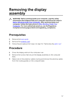
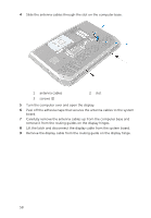
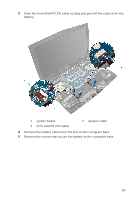
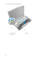
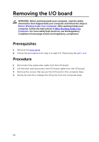
Replacing the display assembly WARNING: Before working inside your computer, read the safety information that shipped with your computer and follow the steps in Before Working Inside Your Computer. After working inside your computer, follow the instructions in After Working Inside Your Computer. For more safety best practices, see the Regulatory Compliance home page at dell.com/regulatory_compliance. Procedure 1 Align the screw holes on the display hinges with the screw holes on the computer base. 2 Replace the screws that secure the display assembly to the computer base. 3 Route the logo-board cable through the routing guide on the display hinge and connect the logo-board cable to the system board. 4 Route the display cable through the routing guide on the display hinge. 5 Slide the display cable into the connector on the system board and press down on the latch to secure the cable. 6 Route the antenna cables through the routing guide on the display hinge and on the computer base. 7 Adhere the adhesive tapes that secure the antenna cables to the system board. 8 Close the display and turn the computer over. 9 Replace the screws that secure the display assembly to the computer base. Post-requisites 1 Follow the procedure from step 5 to step 11 in "Replacing the palm rest". 2 Replace the wireless card. 3 Replace the base panel. 61
-
 1
1 -
2
-
3
-
4
-
5
-
6
-
7
-
8
-
9
-
10
-
11
-
12
-
13
-
14
-
15
-
16
-
17
-
18
-
19
-
20
-
21
-
22
-
23
-
24
-
25
-
26
-
27
-
28
-
29
-
30
-
31
-
32
-
33
-
34
-
35
-
36
-
37
-
38
-
39
-
40
-
41
-
42
-
43
-
44
-
45
-
46
-
47
-
48
-
49
-
50
-
51
-
52
-
53
-
54
-
55
-
 56
56 -
 57
57 -
 58
58 -
 59
59 -
 60
60 -
 61
61 -
 62
62 -
 63
63 -
 64
64 -
 65
65 -
 66
66 -
67
-
68
-
69
-
70
-
71
-
72
-
73
-
74
-
75
-
76
-
77
-
78
-
79
-
80
-
81
-
82
-
83
-
84
-
85
-
86
-
87
-
88
-
89
-
90
-
91
-
92
-
93
-
94
-
95
-
96
-
97
-
98
-
99
-
100
-
101
-
102
-
103
-
104
-
105
-
106
-
107
-
108
-
109
-
110
-
111
-
112
-
113
-
114
-
115
-
116
-
117
-
118
-
119
-
120
-
121
-
122
-
123
-
124
-
125
-
126
-
127
-
128
-
129
-
130
-
131
-
132
-
133
-
134
-
135
-
136
-
137
-
138
-
139
-
140
-
141
-
142
-
143
-
144
-
145
 |
 |