Dell Alienware 17 R2 Service Manual - Page 130
Replacing the Alienware AlienHead LED board, Procedure, Post-requisites
 |
View all Dell Alienware 17 R2 manuals
Add to My Manuals
Save this manual to your list of manuals |
Page 130 highlights
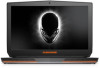
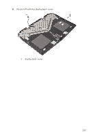
Replacing the Alienware AlienHead LED board WARNING: Before working inside your computer, read the safety information that shipped with your computer and follow the steps in Before Working Inside Your Computer. After working inside your computer, follow the instructions in After Working Inside Your Computer. For more safety best practices, see the Regulatory Compliance home page at dell.com/regulatory_compliance. Procedure 1 Connect the camera cable to the camera module. 2 Adhere the Alienware AlienHead LED board and display-board cable to the display back-cover. 3 Adhere the mylar to secure the Alienware AlienHead LED board and display-board cable and to the display back-cover. 4 Adhere the mylar to secure the display-board cables and the display- panel AlienFX LEDs to the display back-cover. Post-requisites 1 Replace the display panel. 2 Replace the display bezel. 3 Replace the display assembly. 4 Follow the procedure from step 5 to step 11 in "Replacing the palm rest". 5 Replace the wireless card. 6 Replace the base panel. 130
-
 1
1 -
2
-
3
-
4
-
5
-
6
-
7
-
8
-
9
-
10
-
11
-
12
-
13
-
14
-
15
-
16
-
17
-
18
-
19
-
20
-
21
-
22
-
23
-
24
-
25
-
26
-
27
-
28
-
29
-
30
-
31
-
32
-
33
-
34
-
35
-
36
-
37
-
38
-
39
-
40
-
41
-
42
-
43
-
44
-
45
-
46
-
47
-
48
-
49
-
50
-
51
-
52
-
53
-
54
-
55
-
56
-
57
-
58
-
59
-
60
-
61
-
62
-
63
-
64
-
65
-
66
-
67
-
68
-
69
-
70
-
71
-
72
-
73
-
74
-
75
-
76
-
77
-
78
-
79
-
80
-
81
-
82
-
83
-
84
-
85
-
86
-
87
-
88
-
89
-
90
-
91
-
92
-
93
-
94
-
95
-
96
-
97
-
98
-
99
-
100
-
101
-
102
-
103
-
104
-
105
-
106
-
107
-
108
-
109
-
110
-
111
-
112
-
113
-
114
-
115
-
116
-
117
-
118
-
119
-
120
-
121
-
122
-
123
-
124
-
 125
125 -
 126
126 -
 127
127 -
 128
128 -
 129
129 -
 130
130 -
 131
131 -
 132
132 -
 133
133 -
 134
134 -
 135
135 -
136
-
137
-
138
-
139
-
140
-
141
-
142
-
143
-
144
-
145
 |
 |