Dell Alienware 17 R3 Service Manual
Dell Alienware 17 R3 Manual
 |
View all Dell Alienware 17 R3 manuals
Add to My Manuals
Save this manual to your list of manuals |
Dell Alienware 17 R3 manual content summary:
- Dell Alienware 17 R3 | Service Manual - Page 1
Alienware 17 Service Manual Computer Model: Alienware 17 R3 Regulatory Model: P43F Regulatory Type: P43F001 - Dell Alienware 17 R3 | Service Manual - Page 2
potential damage to hardware or loss of data and tells you how to avoid the problem. WARNING: A WARNING indicates a potential for property damage, personal injury, or death. Copyright © 2015 Dell Inc. All rights reserved. This product is protected by U.S. and international copyright and intellectual - Dell Alienware 17 R3 | Service Manual - Page 3
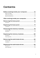
Before working inside your computer 12 Before you begin 12 Safety instructions 12 Recommended tools 13 After working inside your computer 14 Removing the base panel 15 Procedure...15 Replacing the base panel 17 Procedure...17 Removing the memory modules 18 Prerequisites...18 Procedure...18 - Dell Alienware 17 R3 | Service Manual - Page 4
hard drive 28 Procedure...28 Post-requisites 28 Removing the palm rest 29 Prerequisites...29 Procedure...30 Replacing the palm rest 36 Procedure...36 Post-requisites 36 Removing the power-button board 37 Prerequisites...37 Procedure...37 Replacing the power-button board 39 Procedure...39 Post - Dell Alienware 17 R3 | Service Manual - Page 5
pad 51 Procedure...51 Post-requisites 51 Removing the display assembly 52 Prerequisites...52 Procedure...52 Replacing the display assembly 56 Procedure...56 Post-requisites 57 Removing the battery 58 Prerequisites...58 Procedure...58 Replacing the battery 61 Procedure...61 Post-requisites 61 - Dell Alienware 17 R3 | Service Manual - Page 6
I/O board 64 Procedure...64 Post-requisites 64 Removing the speakers 65 Prerequisites...65 Procedure...65 Replacing the speakers 68 Procedure...68 Post-requisites 68 Removing the front AlienFX LED boards 69 Prerequisites...69 Procedure...69 Replacing the front AlienFX LED board 71 Procedure - Dell Alienware 17 R3 | Service Manual - Page 7
83 Procedure...83 Post-requisites 84 Removing the heat sink 85 Prerequisites...85 Procedure...85 Replacing the heat sink 87 Procedure...87 Post-requisites 87 Removing the coin-cell battery 88 Prerequisites...88 Procedure...88 Replacing the coin-cell battery 90 Procedure...90 Post-requisites - Dell Alienware 17 R3 | Service Manual - Page 8
-adapter port 96 Procedure...96 Post-requisites 96 Removing the subwoofer 97 Prerequisites...97 Procedure...97 Replacing the subwoofer 99 Procedure...99 Post-requisites 99 Removing the display bezel 100 Prerequisites 100 Procedure...100 Replacing the display bezel 105 Procedure...105 Post - Dell Alienware 17 R3 | Service Manual - Page 9
109 Procedure...109 Post-requisites 109 Removing the display hinges 110 Prerequisites...110 Procedure...110 Replacing the display hinges 113 Procedure...113 Post-requisites 113 Removing the computer base 114 Prerequisites...114 Procedure...114 Replacing the computer base 116 Procedure...116 - Dell Alienware 17 R3 | Service Manual - Page 10
-panel AlienFX LEDs 127 Procedure...127 Post-requisites 127 Removing the Alienware AlienHead LED board.. 128 Prerequisites 128 Procedure...128 Replacing the Alienware AlienHead LED board.... 131 Procedure...131 Post-requisites 131 Removing the display back-cover 132 Prerequisites 132 Procedure - Dell Alienware 17 R3 | Service Manual - Page 11
136 Overview...136 Entering BIOS setup program 136 BIOS setup program options 136 Boot sequence 142 Boot options 142 Changing boot sequence for the current boot 143 Changing boot sequence for future boots 143 Flashing the BIOS 144 Getting help and contacting Alienware 145 Self-help resources - Dell Alienware 17 R3 | Service Manual - Page 12
→ Power → Shut down. - Windows 8.1: On the Start screen, click or tap the power icon → Shut down. - Windows Remove any media card and optical disc from your computer, if applicable. Safety instructions best practices, see the Regulatory Compliance home page at www.dell.com/regulatory_compliance. 12 - Dell Alienware 17 R3 | Service Manual - Page 13
After you finish working inside the computer, replace all covers, panels, and screws before troubleshooting and repairs as authorized or directed by the Dell technical assistance team. Damage due to servicing that is not authorized by Dell is not covered by your warranty. See the safety instructions - Dell Alienware 17 R3 | Service Manual - Page 14
screws remain inside your computer. 2 Connect any external devices, peripherals, and cables you removed before working on your computer. 3 Replace any media cards, discs, and any other parts that you removed before working on your computer. 4 Connect your computer and all attached devices to their - Dell Alienware 17 R3 | Service Manual - Page 15
working inside your computer. After working inside your computer, follow the instructions in After working inside your computer. For more safety best practices, see the Regulatory Compliance home page at www.dell.com/regulatory_compliance. Procedure 1 Close the display and turn the computer over - Dell Alienware 17 R3 | Service Manual - Page 16
5 Disconnect the battery cable from the system board. 1 battery cable 6 Turn the computer over. 7 Press and hold the power button for 5 seconds to ground the system board. 16 - Dell Alienware 17 R3 | Service Manual - Page 17
your computer. After working inside your computer, follow the instructions in After working inside your computer. For more safety best practices, see the Regulatory Compliance home page at www.dell.com/regulatory_compliance. Procedure 1 Connect the battery cable to the system board. 2 Slide the tabs - Dell Alienware 17 R3 | Service Manual - Page 18
your computer. After working inside your computer, follow the instructions in After working inside your computer. For more safety best practices, see the Regulatory Compliance home page at www.dell.com/regulatory_compliance. Prerequisites Remove the base panel. Procedure 1 Using your fingertips - Dell Alienware 17 R3 | Service Manual - Page 19
2 Slide and remove the memory module from the memory-module slot. 1 securing clips (2) 3 memory-module slot 2 memory modules (2) 19 - Dell Alienware 17 R3 | Service Manual - Page 20
Before working inside your computer. After working inside your computer, follow the instructions in After working inside your computer. For more safety best practices, see the Regulatory Compliance home page at www.dell.com/regulatory_compliance. Procedure 1 Align the notch on the memory module with - Dell Alienware 17 R3 | Service Manual - Page 21
into the slot at an angle and press the memory module down until it clicks into place. NOTE: If you do not hear the click, remove the memory module and reinstall it. 1 securing clips (2) 3 memory-module slot 5 tab Post-requisites Replace the base panel. 2 memory module 4 notch 21 - Dell Alienware 17 R3 | Service Manual - Page 22
working inside your computer. After working inside your computer, follow the instructions in After working inside your computer. For more safety best practices, see the Regulatory Compliance home page at www.dell.com/regulatory_compliance. CAUTION: Solid-state drives are fragile. Exercise care when - Dell Alienware 17 R3 | Service Manual - Page 23
2 Slide and remove the solid-state drive from the solid-state drive slot. 1 solid-state drive slot 3 screw 2 solid-state drive 23 - Dell Alienware 17 R3 | Service Manual - Page 24
working inside your computer. After working inside your computer, follow the instructions in After working inside your computer. For more safety best practices, see the Regulatory Compliance home page at www.dell.com/regulatory_compliance. CAUTION: Solid-state drives are fragile. Exercise care when - Dell Alienware 17 R3 | Service Manual - Page 25
instructions in After working inside your computer. For more safety best practices, see the Regulatory Compliance home page at www.dell Note the hard-drive cable routing and remove the cable from the routing guides on the computer base. 3 Remove the screws that secure the hard-drive assembly to the - Dell Alienware 17 R3 | Service Manual - Page 26
4 Lift the hard-drive assembly off the computer base. 1 pull tab 3 screws (4) 2 hard-drive cable 4 hard-drive assembly 5 Remove the screws that secure the hard-drive bracket to the hard drive. 6 Lift the hard-drive bracket off the hard-drive assembly. 1 hard drive 3 screws (4) - Dell Alienware 17 R3 | Service Manual - Page 27
7 Disconnect the interposer from the hard drive. 1 interposer 2 hard drive 27 - Dell Alienware 17 R3 | Service Manual - Page 28
instructions in After working inside your computer. For more safety best practices, see the Regulatory Compliance home page at www.dell computer base. 5 Replace the screws that secure the hard-drive assembly to the computer base. 6 Route the hard-drive cable through the routing guides on the computer - Dell Alienware 17 R3 | Service Manual - Page 29
the steps in Before working inside your computer. After working inside your computer, follow the instructions in After working inside your computer. For more safety best practices, see the Regulatory Compliance home page at www.dell.com/regulatory_compliance. Prerequisites Remove the base panel. 29 - Dell Alienware 17 R3 | Service Manual - Page 30
Procedure 1 Lift the latches and disconnect the keyboard cable, keyboard-backlight cable, macro-keys cable and macro-keys backlight cable from the system board. 1 keyboard-backlight cable 3 macro-keys cable 5 macro-keys backlight cable 2 keyboard cable 4 latches (4) 30 - Dell Alienware 17 R3 | Service Manual - Page 31
2 Remove the screws that secure the palm-rest assembly to the computer base. 1 computer base 2 screws (16) 31 - Dell Alienware 17 R3 | Service Manual - Page 32
3 Lift the computer base slightly and push the palm-rest assembly through the slot on the computer base to release the tabs on the palm-rest assembly. 1 slot 2 palm-rest assembly 4 Turn the computer over and open the display as far as possible. 5 Using a plastic scribe, pry up along the edges of - Dell Alienware 17 R3 | Service Manual - Page 33
6 Gently lift the palm-rest assembly and turn it over. 1 plastic scribe 2 palm-rest assembly 7 Peel the tape that secures the power-button board cable to the system board. 8 Disconnect the power-button board cable from the system board. 33 - Dell Alienware 17 R3 | Service Manual - Page 34
9 Lift the palm-rest assembly off the computer base. 1 palm-rest assembly 3 latch 10 Remove the power-button board. 11 Remove the status-light board. 12 Remove the keyboard. 2 power-button board cable 34 - Dell Alienware 17 R3 | Service Manual - Page 35
13 Remove the touch pad. 1 palm rest 35 - Dell Alienware 17 R3 | Service Manual - Page 36
, follow the instructions in After working inside your computer. For more safety best practices, see the Regulatory Compliance home page at www.dell.com/regulatory_compliance. Procedure 1 Replace the touch pad. 2 Replace the keyboard. 3 Replace the status-light board. 4 Replace the power-button - Dell Alienware 17 R3 | Service Manual - Page 37
your computer. After working inside your computer, follow the instructions in After working inside your computer. For more safety best practices, see the Regulatory Compliance home page at www.dell.com/regulatory_compliance. Prerequisites 1 Remove the base panel. 2 Follow the procedure from step - Dell Alienware 17 R3 | Service Manual - Page 38
4 Lift the power-button board off the palm-rest assembly. 1 power-button board cable 3 touch-pad cable 5 screws (2) 2 latches (2) 4 status-light cable 6 power-button board 38 - Dell Alienware 17 R3 | Service Manual - Page 39
the instructions in After working inside your computer. For more safety best practices, see the Regulatory Compliance home page at www.dell.com/regulatory_compliance. Procedure 1 Align the screw holes on the power-button board with the screw holes on the palm-rest assembly. 2 Replace the screws - Dell Alienware 17 R3 | Service Manual - Page 40
your computer. After working inside your computer, follow the instructions in After working inside your computer. For more safety best practices, see the Regulatory Compliance home page at www.dell.com/regulatory_compliance. Prerequisites 1 Remove the base panel. 2 Follow the procedure from step - Dell Alienware 17 R3 | Service Manual - Page 41
3 Lift the status-light board off the palm-rest assembly. 1 screws (2) 3 status-light board cable 2 latch 4 status-light board 41 - Dell Alienware 17 R3 | Service Manual - Page 42
the instructions in After working inside your computer. For more safety best practices, see the Regulatory Compliance home page at www.dell.com/regulatory_compliance. Procedure 1 Align the screw holes on the status-light board with the screw holes on the palm-rest assembly. 2 Replace the screws - Dell Alienware 17 R3 | Service Manual - Page 43
your computer. After working inside your computer, follow the instructions in After working inside your computer. For more safety best practices, see the Regulatory Compliance home page at www.dell.com/regulatory_compliance. Prerequisites 1 Remove the base panel. 2 Follow the procedure from step - Dell Alienware 17 R3 | Service Manual - Page 44
cable and status-light cable routing and peel off the cables from the keyboard bracket. 1 latches (2) 2 touch-pad cable 3 status-light cable 3 Remove the screws that secure the keyboard bracket to the palm-rest assembly. 4 Slide the keyboard cable, keyboard-backlight cable, macro-keys cable and - Dell Alienware 17 R3 | Service Manual - Page 45
5 Lift the keyboard bracket off the palm-rest assembly. 1 screws (14) 3 palm-rest assembly 2 keyboard bracket 6 Remove the screws that secure the keyboard to the palm-rest assembly. 7 Release the tabs that secure the keyboard to the palm-rest assembly. 45 - Dell Alienware 17 R3 | Service Manual - Page 46
8 Slide and lift the keyboard along with the cables off the palm-rest assembly. 1 tabs (5) 3 screws (2) 2 keyboard 46 - Dell Alienware 17 R3 | Service Manual - Page 47
instructions in After working inside your computer. For more safety best practices, see the Regulatory Compliance home page at www.dell. on the keyboard bracket with the screw holes on the palm-rest assembly. 6 Replace the screws that secure the keyboard bracket to the palm-rest assembly. 7 Adhere - Dell Alienware 17 R3 | Service Manual - Page 48
your computer. After working inside your computer, follow the instructions in After working inside your computer. For more safety best practices, see the Regulatory Compliance home page at www.dell.com/regulatory_compliance. Prerequisites 1 Remove the base panel. 2 Follow the procedure from step - Dell Alienware 17 R3 | Service Manual - Page 49
Procedure 1 Lift the latches and disconnect the touch-pad cable and touch-pad button cable from the touch pad. 1 touch-pad cable 3 touch-pad button cable 2 latches (2) 2 Remove the screws that secure the touch-pad button bracket to the palmrest assembly. 49 - Dell Alienware 17 R3 | Service Manual - Page 50
3 Lift the touch-pad button bracket off the palm-rest assembly. 1 touch-pad button bracket 2 screws (5) 4 Lift the touch pad off the palm-rest assembly. 1 touch pad 50 - Dell Alienware 17 R3 | Service Manual - Page 51
instructions in After working inside your computer. For more safety best practices, see the Regulatory Compliance home page at www.dell. touch-pad button bracket with the screw holes on the palm-rest assembly. 4 Replace the screws that secure the touch-pad button bracket to the palmrest assembly. 5 - Dell Alienware 17 R3 | Service Manual - Page 52
your computer. After working inside your computer, follow the instructions in After working inside your computer. For more safety best practices, see the Regulatory Compliance home page at www.dell.com/regulatory_compliance. Prerequisites 1 Remove the base panel. 2 Follow the procedure from step - Dell Alienware 17 R3 | Service Manual - Page 53
open the display. 7 Peel off the adhesive tape that secures the antenna cables to the system board. 8 Carefully remove the antenna cables up from the computer base and remove it from the routing guides on the display hinges. 9 Lift the latch and disconnect the display cable from the system board. 10 - Dell Alienware 17 R3 | Service Manual - Page 54
11 Disconnect the logo-board cable from the system board and remove it from the routing guide on the display hinge. 1 display cable 3 connector 5 antenna cables 2 latch 4 logo-board cable 6 tape 12 Remove the screws that secure the display assembly to the computer base. 54 - Dell Alienware 17 R3 | Service Manual - Page 55
13 Lift the display assembly off the computer base. 1 display assembly 3 computer base 2 screws (4) 4 display hinges (2) 55 - Dell Alienware 17 R3 | Service Manual - Page 56
instructions in After working inside your computer. For more safety best practices, see the Regulatory Compliance home page at www.dell.com/regulatory_compliance. Procedure 1 Align the screw holes on the display hinges with the screw holes on the computer base. 2 Replace card supported by your - Dell Alienware 17 R3 | Service Manual - Page 57
11 Replace the screws that secure the display assembly to the computer base. Post-requisites 1 Follow the procedure from step 5 to step 11 in "Replacing the palm rest". 2 Replace the base panel. 57 - Dell Alienware 17 R3 | Service Manual - Page 58
your computer. After working inside your computer, follow the instructions in After working inside your computer. For more safety best practices, see the Regulatory Compliance home page at www.dell.com/regulatory_compliance. Prerequisites 1 Remove the base panel. 2 Follow the procedure from step - Dell Alienware 17 R3 | Service Manual - Page 59
3 Note the front AlienFX LED cable routing and peel off the cable from the battery. 1 system board 3 front AlienFX LED cable 2 speaker cable 4 Remove the battery cable from the slot on the computer base. 5 Remove the screws that secure the battery to the computer base. 59 - Dell Alienware 17 R3 | Service Manual - Page 60
6 Lift the battery off the computer base. 1 battery cable 3 screws (6) 2 battery 60 - Dell Alienware 17 R3 | Service Manual - Page 61
instructions in After working inside your computer. For more safety best practices, see the Regulatory Compliance home page at www.dell.com/regulatory_compliance. Procedure 1 Align the screw holes on the battery with the screw holes on the computer base. 2 Replace the screws that secure the battery - Dell Alienware 17 R3 | Service Manual - Page 62
your computer. After working inside your computer, follow the instructions in After working inside your computer. For more safety best practices, see the Regulatory Compliance home page at www.dell.com/regulatory_compliance. Prerequisites 1 Remove the base panel. 2 Follow the procedure from step - Dell Alienware 17 R3 | Service Manual - Page 63
5 Lift the I/O board off the computer base. 1 subwoofer cable 3 I/O-board cable 5 I/O board 2 latch 4 screws (2) 63 - Dell Alienware 17 R3 | Service Manual - Page 64
Before working inside your computer. After working inside your computer, follow the instructions in After working inside your computer. For more safety best practices, see the Regulatory Compliance home page at www.dell.com/regulatory_compliance. Procedure 1 Align the ports on the I/O board with the - Dell Alienware 17 R3 | Service Manual - Page 65
your computer. After working inside your computer, follow the instructions in After working inside your computer. For more safety best practices, see the Regulatory Compliance home page at www.dell.com/regulatory_compliance. Prerequisites 1 Remove the base panel. 2 Follow the procedure from step - Dell Alienware 17 R3 | Service Manual - Page 66
2 Note the front AlienFX LED cable routing and peel off the cable from the battery. 1 connector 2 front AlienFX LED cable 3 Disconnect the speaker cable from the system board. 4 Remove the speaker cable from the routing guides on the battery and computer base. 66 - Dell Alienware 17 R3 | Service Manual - Page 67
5 Lift the speakers along with its cable off the computer base. 1 speaker cable 3 alignment posts (4) 5 speakers (2) 2 system board 4 computer base 6 routing guides 67 - Dell Alienware 17 R3 | Service Manual - Page 68
working inside your computer. After working inside your computer, follow the instructions in After working inside your computer. For more safety best practices, see the Regulatory Compliance home page at www.dell.com/regulatory_compliance. Procedure 1 Using the alignment posts, place the speakers on - Dell Alienware 17 R3 | Service Manual - Page 69
your computer. After working inside your computer, follow the instructions in After working inside your computer. For more safety best practices, see the Regulatory Compliance home page at www.dell.com/regulatory_compliance. Prerequisites 1 Remove the base panel. 2 Follow the procedure from step - Dell Alienware 17 R3 | Service Manual - Page 70
3 Lift the front AlienFX LED boards off the computer base. 1 front AlienFX LED boards (2) 3 screws (2) 2 front AlienFX LED board cables (2) 70 - Dell Alienware 17 R3 | Service Manual - Page 71
working inside your computer. After working inside your computer, follow the instructions in After working inside your computer. For more safety best practices, see the Regulatory Compliance home page at www.dell.com/regulatory_compliance. Procedure 1 Using the alignment posts on the computer base - Dell Alienware 17 R3 | Service Manual - Page 72
your computer. After working inside your computer, follow the instructions in After working inside your computer. For more safety best practices, see the Regulatory Compliance home page at www.dell.com/regulatory_compliance. Prerequisites 1 Remove the base panel. 2 Follow the procedure from step - Dell Alienware 17 R3 | Service Manual - Page 73
3 Turn the computer over and open the display. 4 Remove the screws that secure the processor fan to the computer base. 5 Peel off the Mylar from the processor heat-sink and processor fan. 6 Slide and lift the processor fan off the computer base. 1 mylar 3 screws (2) 2 processor fan 73 - Dell Alienware 17 R3 | Service Manual - Page 74
instructions in After working inside your computer. For more safety best practices, see the Regulatory Compliance home page at www.dell base. 3 Adhere the Mylar on the processor fan and processor heat-sink. 4 Replace the screws that secure the processor fan to the computer base. 5 Close the display - Dell Alienware 17 R3 | Service Manual - Page 75
safety best practices, see the Regulatory Compliance home page at www.dell.com/regulatory_compliance. NOTE: Your computer's Service Tag is stored in the system board. You must enter the Service Tag in the BIOS setup program after you replace the system board. NOTE: Replacing the system board removes - Dell Alienware 17 R3 | Service Manual - Page 76
2 Disconnect the processor-fan cable, video-card fan cable, hard-drive cable and power-adapter port cable from the system board. 1 processor-fan cable 3 video-card fan cable 5 hard-drive cable 2 power-adapter port cable 4 system board 3 Turn the computer over. 4 Disconnect the speaker and front - Dell Alienware 17 R3 | Service Manual - Page 77
5 Lift the latch and disconnect the I/O-board cable from the system board. 1 I/O-board cable 3 system board 5 front AlienFX LED cable 2 latch 4 speaker cable 6 Remove the screws that secure the system board to the computer base. 77 - Dell Alienware 17 R3 | Service Manual - Page 78
7 Lift the system board off the computer base. 1 screws (6) 8 Remove the wireless card. 9 Remove the heat sink. 10 Remove the coin-cell battery. 2 system board 78 - Dell Alienware 17 R3 | Service Manual - Page 79
safety best practices, see the Regulatory Compliance home page at www.dell.com/regulatory_compliance. NOTE: Your computer's Service Tag is stored in the system board. You must enter the Service Tag in the BIOS setup program after you replace the system board. NOTE: Replacing the system board removes - Dell Alienware 17 R3 | Service Manual - Page 80
3 Replace the base panel. 80 - Dell Alienware 17 R3 | Service Manual - Page 81
your computer. After working inside your computer, follow the instructions in After working inside your computer. For more safety best practices, see the Regulatory Compliance home page at www.dell.com/regulatory_compliance. Prerequisites 1 Remove the base panel. 2 Follow the procedure from step - Dell Alienware 17 R3 | Service Manual - Page 82
2 Lift and slide the wireless card from the wireless-card slot. 1 wireless card 2 wireless-card slot 82 - Dell Alienware 17 R3 | Service Manual - Page 83
working inside your computer. After working inside your computer, follow the instructions in After working inside your computer. For more safety best practices, see the Regulatory Compliance home page at www.dell.com/regulatory_compliance. Procedure CAUTION: To avoid damaging the wireless card, do - Dell Alienware 17 R3 | Service Manual - Page 84
to adhere the wireless card to the system board. 1 wireless card 2 wireless-card slot Post-requisites 1 Follow the procedure from step 4 to step 10 in "Replacing the system board". 2 Replace the display assembly. 3 Follow the procedure from step 5 to step 11 in - Dell Alienware 17 R3 | Service Manual - Page 85
instructions in After working inside your computer. For more safety best practices, see the Regulatory Compliance home page at www.dell Prerequisites 1 Remove the base panel. 2 Remove the wireless card. 3 Follow the procedure from step 1 to step 9 in "Removing the palm rest". 4 Remove the display - Dell Alienware 17 R3 | Service Manual - Page 86
2 Lift the heat sink off the system board. 1 system board 3 heat sink 2 captive screws (8) 86 - Dell Alienware 17 R3 | Service Manual - Page 87
follow the instructions in After working inside your computer. For more safety best practices, see the Regulatory Compliance home page at www.dell.com/ procedure from step 4 to step 10 in "Replacing the system board". 2 Replace the display assembly. 3 Follow the procedure from step 5 to step 11 in - Dell Alienware 17 R3 | Service Manual - Page 88
working inside your computer, follow the instructions in After working inside your computer. For more safety best practices, see the Regulatory Compliance home page at www.dell.com/regulatory_compliance. CAUTION: Removing the coin-cell battery resets the BIOS setup program's settings to default. It - Dell Alienware 17 R3 | Service Manual - Page 89
2 Peel the coin-cell battery off the system board. 1 coin-cell battery 2 coin-cell battery cable 89 - Dell Alienware 17 R3 | Service Manual - Page 90
computer. After working inside your computer, follow the instructions in After working inside your computer. For more safety best practices, see the Regulatory Compliance home page at www.dell.com/regulatory_compliance. Procedure 1 Adhere the coin-cell battery to the system board. 2 Connect the coin - Dell Alienware 17 R3 | Service Manual - Page 91
After working inside your computer, follow the instructions in After working inside your computer. For more safety best practices, see the Regulatory Compliance home page at www.dell.com/regulatory_compliance. Prerequisites 1 Remove the base panel. 2 Remove the wireless card. 3 Follow the procedure - Dell Alienware 17 R3 | Service Manual - Page 92
2 Lift the video-card fan off the computer base. 1 screws (2) 2 video-card fan 92 - Dell Alienware 17 R3 | Service Manual - Page 93
, follow the instructions in After working inside your computer. For more safety best practices, see the Regulatory Compliance home page at www.dell.com/regulatory_compliance. Procedure 1 Align the screw holes on the video-card fan with the screw holes on the computer base. 2 Replace the screws that - Dell Alienware 17 R3 | Service Manual - Page 94
After working inside your computer, follow the instructions in After working inside your computer. For more safety best practices, see the Regulatory Compliance home page at www.dell.com/regulatory_compliance. Prerequisites 1 Remove the base panel. 2 Remove the wireless card. 3 Follow the procedure - Dell Alienware 17 R3 | Service Manual - Page 95
4 Lift the power-adapter port along with its cable off the computer base. 1 screws (2) 3 power-adapter port 2 power-adapter port bracket 95 - Dell Alienware 17 R3 | Service Manual - Page 96
instructions in After working inside your computer. For more safety best practices, see the Regulatory Compliance home page at www.dell the routing guides on the computer base. Post-requisites 1 Follow the procedure from step 4 to step 10 in "Replacing the system board". 2 Replace the display - Dell Alienware 17 R3 | Service Manual - Page 97
After working inside your computer, follow the instructions in After working inside your computer. For more safety best practices, see the Regulatory Compliance home page at www.dell.com/regulatory_compliance. Prerequisites 1 Remove the base panel. 2 Remove the wireless card. 3 Follow the procedure - Dell Alienware 17 R3 | Service Manual - Page 98
2 Lift the subwoofer off the computer base. 1 screws (2) 2 subwoofer 98 - Dell Alienware 17 R3 | Service Manual - Page 99
, follow the instructions in After working inside your computer. For more safety best practices, see the Regulatory Compliance home page at www.dell.com/regulatory_compliance. Procedure 1 Align the screw holes on the subwoofer with the screw holes on the computer base. 2 Replace the screws that - Dell Alienware 17 R3 | Service Manual - Page 100
follow the instructions in After working inside your computer. For more safety best practices, see the Regulatory Compliance home page at www.dell.com/regulatory_compliance. Prerequisites NOTE: This chapter is applicable only if you have purchased a laptop with non-touchscreen display. 1 Remove the - Dell Alienware 17 R3 | Service Manual - Page 101
2 Carefully lift the display bezel and turn it over. 1 display bezel 3 Lift the latches and disconnect the display-board cables from the logo board. 101 - Dell Alienware 17 R3 | Service Manual - Page 102
4 Lift the display-bezel assembly away from the display assembly. 1 display bezel 3 latches (3) 2 logo board 4 display-board cables (3) 5 Peel off the tape that secures the logo-board cable to the logo board and disconnect the logo-board cable. 102 - Dell Alienware 17 R3 | Service Manual - Page 103
6 Peel off the logo board from the display bezel. 1 display bezel 3 plastic scribe 5 tape 2 logo board 4 logo-board cable 103 - Dell Alienware 17 R3 | Service Manual - Page 104
7 After performing the above steps, we are left with the display bezel. 1 display bezel 104 - Dell Alienware 17 R3 | Service Manual - Page 105
your computer, follow the instructions in After working inside your computer. For more safety best practices, see the Regulatory Compliance home page at www.dell.com/regulatory_compliance. Procedure NOTE: This chapter is applicable only if you have purchased a laptop with non-touchscreen display - Dell Alienware 17 R3 | Service Manual - Page 106
follow the instructions in After working inside your computer. For more safety best practices, see the Regulatory Compliance home page at www.dell.com/regulatory_compliance. Prerequisites NOTE: This chapter is applicable only if you have purchased a laptop with non-touchscreen display. 1 Remove the - Dell Alienware 17 R3 | Service Manual - Page 107
2 Gently lift the display panel and turn it over. 1 screws (4) 3 display back-cover 2 display panel 3 Lift the latch and disconnect the display cable from the display panel. 107 - Dell Alienware 17 R3 | Service Manual - Page 108
4 Lift the display panel off the display assembly. 1 display panel 3 display cable 2 latch 108 - Dell Alienware 17 R3 | Service Manual - Page 109
your computer, follow the instructions in After working inside your computer. For more safety best practices, see the Regulatory Compliance home page at www.dell.com/regulatory_compliance. Procedure NOTE: This chapter is applicable only if you have purchased a laptop with non-touchscreen display - Dell Alienware 17 R3 | Service Manual - Page 110
follow the instructions in After working inside your computer. For more safety best practices, see the Regulatory Compliance home page at www.dell.com/regulatory_compliance. Prerequisites NOTE: This chapter is applicable only if you have purchased a laptop with non-touchscreen display. 1 Remove the - Dell Alienware 17 R3 | Service Manual - Page 111
2 Lift the hinge caps off the display hinges. 1 hinge caps (2) 2 screws (2) 3 Remove the screws that secure the display hinges to the display backcover. 111 - Dell Alienware 17 R3 | Service Manual - Page 112
4 Lift the display hinges off the display back-cover. 1 display hinges (2) 2 screws (6) 112 - Dell Alienware 17 R3 | Service Manual - Page 113
your computer, follow the instructions in After working inside your computer. For more safety best practices, see the Regulatory Compliance home page at www.dell.com/regulatory_compliance. Procedure NOTE: This chapter is applicable only if you have purchased a laptop with non-touchscreen display - Dell Alienware 17 R3 | Service Manual - Page 114
After working inside your computer, follow the instructions in After working inside your computer. For more safety best practices, see the Regulatory Compliance home page at www.dell.com/regulatory_compliance. Prerequisites 1 Remove the base panel. 2 Remove the wireless card. 3 Follow the procedure - Dell Alienware 17 R3 | Service Manual - Page 115
1 computer base 115 - Dell Alienware 17 R3 | Service Manual - Page 116
. For more safety best practices, see the Regulatory Compliance home page at www.dell.com/regulatory_compliance. Procedure Place the computer base on a flat surface. Post-requisites 1 Replace the subwoofer. 2 Replace the I/O board. 3 Replace the speakers. 4 Replace the battery. 5 Replace the power - Dell Alienware 17 R3 | Service Manual - Page 117
After working inside your computer, follow the instructions in After working inside your computer. For more safety best practices, see the Regulatory Compliance home page at www.dell.com/regulatory_compliance. Prerequisites 1 Remove the base panel. 2 Remove the wireless card. 3 Follow the procedure - Dell Alienware 17 R3 | Service Manual - Page 118
Procedure 1 Lift the latches and disconnect the display-board cables from the logo board. 1 display bezel 3 latches (3) 2 logo board 4 display-board cables (3) 2 Peel off the tape that secures the logo-board cable to the logo board and disconnect the logo-board cable. 118 - Dell Alienware 17 R3 | Service Manual - Page 119
3 Peel off the logo board from the display bezel. 1 display bezel 3 plastic scribe 5 tape 2 logo board 4 logo-board cable 119 - Dell Alienware 17 R3 | Service Manual - Page 120
the instructions in After working inside your computer. For more safety best practices, see the Regulatory Compliance home page at www.dell.com/ to secure the cables. Post-requisites 1 Replace the display bezel. 2 Replace the display assembly. 3 Follow the procedure from step 5 to step 11 - Dell Alienware 17 R3 | Service Manual - Page 121
follow the instructions in After working inside your computer. For more safety best practices, see the Regulatory Compliance home page at www.dell.com/regulatory_compliance. Prerequisites NOTE: This chapter is applicable only if you have purchased a laptop with non-touchscreen display. 1 Remove the - Dell Alienware 17 R3 | Service Manual - Page 122
3 Disconnect the camera cable from the camera module. 1 camera module 3 plastic scribe 5 connector 2 tape 4 camera cable 122 - Dell Alienware 17 R3 | Service Manual - Page 123
your computer, follow the instructions in After working inside your computer. For more safety best practices, see the Regulatory Compliance home page at www.dell.com/regulatory_compliance. Procedure NOTE: This chapter is applicable only if you have purchased a laptop with non-touchscreen display - Dell Alienware 17 R3 | Service Manual - Page 124
After working inside your computer, follow the instructions in After working inside your computer. For more safety best practices, see the Regulatory Compliance home page at www.dell.com/regulatory_compliance. Prerequisites 1 Remove the base panel. 2 Remove the wireless card. 3 Follow the procedure - Dell Alienware 17 R3 | Service Manual - Page 125
Procedure 1 Peel off the mylar that secures the display-board cables and the displaypanel AlienFX LEDs to the display back-cover. 1 mylar 125 - Dell Alienware 17 R3 | Service Manual - Page 126
2 Lift the display-board cables and the display-panel AlienFX LEDs off the display back-cover. 1 display back-cover 3 display-panel AlienFX LEDs (2) 2 display-board cables (2) 126 - Dell Alienware 17 R3 | Service Manual - Page 127
instructions in After working inside your computer. For more safety best practices, see the Regulatory Compliance home page at www.dell. to the display back-cover. Post-requisites 1 Replace the display panel. 2 Replace the display bezel. 3 Replace the display assembly. 4 Follow the procedure from step - Dell Alienware 17 R3 | Service Manual - Page 128
After working inside your computer, follow the instructions in After working inside your computer. For more safety best practices, see the Regulatory Compliance home page at www.dell.com/regulatory_compliance. Prerequisites 1 Remove the base panel. 2 Remove the wireless card. 3 Follow the procedure - Dell Alienware 17 R3 | Service Manual - Page 129
3 Peel off the mylar to access the Alienware AlienHead LED board. 1 mylar 3 camera cable 5 camera module 2 display back-cover 4 connector 129 - Dell Alienware 17 R3 | Service Manual - Page 130
4 Lift the display-board cable and Alienware AlienHead LED board off the display back-cover. 1 display-board cable 3 display back-cover 2 Alienware AlienHead LED board 130 - Dell Alienware 17 R3 | Service Manual - Page 131
your computer, follow the instructions in After working inside your computer. For more safety best practices, see the Regulatory Compliance home page at www.dell.com/regulatory_compliance. Procedure 1 Connect the camera cable to the camera module. 2 Adhere the Alienware AlienHead LED board and - Dell Alienware 17 R3 | Service Manual - Page 132
follow the instructions in After working inside your computer. For more safety best practices, see the Regulatory Compliance home page at www.dell.com/regulatory_compliance. Prerequisites NOTE: This chapter is applicable only if you have purchased a laptop with non-touchscreen display. 1 Remove the - Dell Alienware 17 R3 | Service Manual - Page 133
3 Peel the display-board and camera cable off the display back-cover. 1 camera cable 3 camera module 4 Remove the AlienFX Display light. 5 Remove the AlienFX AlienHead board. 2 connector 133 - Dell Alienware 17 R3 | Service Manual - Page 134
6 We are left with the display back-cover. 1 display back-cover 134 - Dell Alienware 17 R3 | Service Manual - Page 135
the instructions in After working inside your computer. For more safety best practices, see the Regulatory Compliance home page at www.dell.com/regulatory_compliance. Procedure NOTE: This chapter is applicable only if you have purchased a laptop with non-touchscreen display. 1 Replace the AlienFX - Dell Alienware 17 R3 | Service Manual - Page 136
, it is recommended that you write down the BIOS setup program screen information for future reference. Use BIOS setup program to: • Get information about the hardware installed in your computer, such as the amount of RAM, the size of the hard drive, and so on. • Change the system configuration - Dell Alienware 17 R3 | Service Manual - Page 137
the current time in hh:mm:ss format. Displays the current date in mm/dd/ yyyy format. Displays the BIOS version. Displays the model number of your computer. Displays the service tag of your computer. Displays the asset tag of your computer. Displays the processor type. Displays the processor speed - Dell Alienware 17 R3 | Service Manual - Page 138
you to enable or disable the USB emulation feature. This feature defines how the BIOS, in the absence of a USBaware operating system, handles USB devices. USB emulation this option is disabled. Allows you to charge USB devices when the computer is turned off or in standby mode. Default: Enabled - Dell Alienware 17 R3 | Service Manual - Page 139
that are not supported by your computer. Default: Enabled Allows you to set function key or multimedia key as the default function key behavior. Default: Function key Allows you to charge your computer battery using Standard Charge or Express Charge mode. Default: Express Charge Allows you to - Dell Alienware 17 R3 | Service Manual - Page 140
Advanced-Performance options with Alienware Graphics Amplifier Overclocking Feature Allows you to enable or disable global overclocking feature. Default: Disabled NOTE: The following features are available only when the Overclocking Feature is enabled. Non-Turbo Flex Support Allows you to - Dell Alienware 17 R3 | Service Manual - Page 141
. Displays a field to input the Service Tag manually when the Service Tag is absent. NOTE: The Service Tag option is available only when the Service Tag is not set. Allows you to set the administrator password. The administrator password controls access to the BIOS setup program utility. Allows you - Dell Alienware 17 R3 | Service Manual - Page 142
Reset Discard Changes and Reset Restore Defaults Discard Changes Save Changes Allows you to exit the BIOS setup program and save your changes. Allows you to exit the BIOS setup program and load previous values for all BIOS drive to run Alienware Diagnostics from the Drivers and Utilities disc or - Dell Alienware 17 R3 | Service Manual - Page 143
When F12 Boot Options appear in the lower-right corner of the screen, press F12. The BIOS detects the device and adds the USB flash option to the boot When F2 Setup, F12 Boot Options appear in the lower-right corner of the screen, press F12. NOTE: If you wait too long and the operating system logo - Dell Alienware 17 R3 | Service Manual - Page 144
available or when you replace the system board. To flash the BIOS: 1 Turn on the computer. 2 Go to www.dell.com/support. 3 Click Product Support, enter the Service Tag of your computer and click Submit. NOTE: If you do not have the Service Tag, use the auto-detect feature or manually browse for your - Dell Alienware 17 R3 | Service Manual - Page 145
: • Dell Help & Support app (Windows 10/Windows 8.1) • Get started app (Windows 10) • Help+Tips app (Windows 8.1) Information about Alienware products www.alienware.com and services Troubleshooting information, user manuals, setup instructions, product specifications, technical help blogs, drivers - Dell Alienware 17 R3 | Service Manual - Page 146
NOTE: If you do not have an active internet connection, you can find contact information on your purchase invoice, packing slip, bill, or Dell product catalog. 146
-
 1
1 -
 2
2 -
 3
3 -
 4
4 -
 5
5 -
 6
6 -
 7
7 -
8
-
9
-
10
-
11
-
12
-
13
-
14
-
15
-
16
-
17
-
18
-
19
-
20
-
21
-
22
-
23
-
24
-
25
-
26
-
27
-
28
-
29
-
30
-
31
-
32
-
33
-
34
-
35
-
36
-
37
-
38
-
39
-
40
-
41
-
42
-
43
-
44
-
45
-
46
-
47
-
48
-
49
-
50
-
51
-
52
-
53
-
54
-
55
-
56
-
57
-
58
-
59
-
60
-
61
-
62
-
63
-
64
-
65
-
66
-
67
-
68
-
69
-
70
-
71
-
72
-
73
-
74
-
75
-
76
-
77
-
78
-
79
-
80
-
81
-
82
-
83
-
84
-
85
-
86
-
87
-
88
-
89
-
90
-
91
-
92
-
93
-
94
-
95
-
96
-
97
-
98
-
99
-
100
-
101
-
102
-
103
-
104
-
105
-
106
-
107
-
108
-
109
-
110
-
111
-
112
-
113
-
114
-
115
-
116
-
117
-
118
-
119
-
120
-
121
-
122
-
123
-
124
-
125
-
126
-
127
-
128
-
129
-
130
-
131
-
132
-
133
-
134
-
135
-
136
-
137
-
138
-
139
-
140
-
141
-
142
-
143
-
144
-
145
-
146
 |
 |

Alienware 17
Service Manual
Computer Model: Alienware 17 R3
Regulatory Model: P43F
Regulatory Type: P43F001