Dell Alienware 17 R3 Service Manual - Page 56
Replacing the display assembly, Procedure
 |
View all Dell Alienware 17 R3 manuals
Add to My Manuals
Save this manual to your list of manuals |
Page 56 highlights
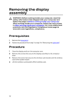
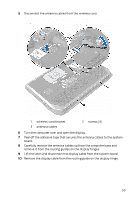
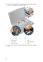
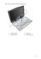
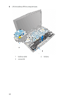
Replacing the display assembly WARNING: Before working inside your computer, read the safety information that shipped with your computer and follow the steps in Before working inside your computer. After working inside your computer, follow the instructions in After working inside your computer. For more safety best practices, see the Regulatory Compliance home page at www.dell.com/regulatory_compliance. Procedure 1 Align the screw holes on the display hinges with the screw holes on the computer base. 2 Replace the screws that secure the display assembly to the computer base. 3 Route the logo-board cable through the routing guide on the display hinge and connect the logo-board cable to the system board. 4 Route the display cable through the routing guide on the display hinge. 5 Slide the display cable into the connector on the system board and press down on the latch to secure the cable. 6 Route the antenna cables through the routing guide on the display hinge and on the computer base. 7 Connect the antenna cables to the wireless card. The following table provides the antenna-cable color scheme for the wireless card supported by your computer. Connectors on the wireless card Main (white triangle) Antenna-cable color White Auxiliary (black triangle) Black 8 Align the screw hole on the wireless-card bracket with the screw hole on the wireless card. 9 Replace the screw that secures the wireless-card bracket with the wireless card. 10 Close the display and turn the computer over. 56
-
 1
1 -
2
-
3
-
4
-
5
-
6
-
7
-
8
-
9
-
10
-
11
-
12
-
13
-
14
-
15
-
16
-
17
-
18
-
19
-
20
-
21
-
22
-
23
-
24
-
25
-
26
-
27
-
28
-
29
-
30
-
31
-
32
-
33
-
34
-
35
-
36
-
37
-
38
-
39
-
40
-
41
-
42
-
43
-
44
-
45
-
46
-
47
-
48
-
49
-
50
-
 51
51 -
 52
52 -
 53
53 -
 54
54 -
 55
55 -
 56
56 -
 57
57 -
 58
58 -
 59
59 -
 60
60 -
 61
61 -
62
-
63
-
64
-
65
-
66
-
67
-
68
-
69
-
70
-
71
-
72
-
73
-
74
-
75
-
76
-
77
-
78
-
79
-
80
-
81
-
82
-
83
-
84
-
85
-
86
-
87
-
88
-
89
-
90
-
91
-
92
-
93
-
94
-
95
-
96
-
97
-
98
-
99
-
100
-
101
-
102
-
103
-
104
-
105
-
106
-
107
-
108
-
109
-
110
-
111
-
112
-
113
-
114
-
115
-
116
-
117
-
118
-
119
-
120
-
121
-
122
-
123
-
124
-
125
-
126
-
127
-
128
-
129
-
130
-
131
-
132
-
133
-
134
-
135
-
136
-
137
-
138
-
139
-
140
-
141
-
142
-
143
-
144
-
145
-
146
 |
 |