Dell Alienware M17x Manual - Page 34
Upgrading/Replacing Memory - memory upgrade
 |
UPC - 074450000071
View all Dell Alienware M17x manuals
Add to My Manuals
Save this manual to your list of manuals |
Page 34 highlights
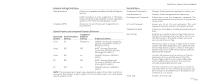
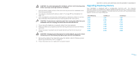
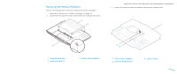
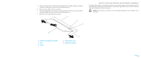
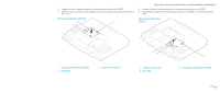
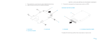
CAUTION: To avoid damaging the notebook, perform the following steps before you begin working inside the notebook. 1. Ensure that the work surface is flat and clean to prevent the notebook cover from being scratched. 2. Turn off your notebook (for details, refer to "Turning Off Your Notebook" on page 33). 3. If the notebook is connected to a docking device (docked), undock it. See the documentation that came with your docking device for instructions. CAUTION: To disconnect a network cable, first unplug the cable from your notebook and then unplug the cable from the network device. 4. Disconnect all telephone or network cables from the notebook. 5. Press and eject any installed cards from the ExpressCard slot and the Media Card slot. 6. Disconnect your notebook and all attached devices from their electrical outlets. CAUTION: To help prevent damage to the system board, you must remove the battery from the battery bay before you service the notebook. CHAPTER 5: INSTALLING ADDITIONAL OR REPLACEMENT COMPONENTS Upgrading/Replacing Memory Your notebook is equipped with a configurable memory unit. The industry standard JEDEC PC3-8500/PC3-10600 (DDR3) SODIMM memory module sockets are available for memory upgrade. The table below illustrates all the possible ways system memory can be configured. Total Memory 2 GB 3 GB 3 GB 4 GB 6 GB 6 GB 8 GB Socket #1 1 GB 2 GB 1 GB 2 GB 2 GB 4 GB 4 GB Socket #2 1 GB 1 GB 2 GB 2 GB 4 GB 2 GB 4 GB 7. Remove the battery from the battery bay (for details, refer to "Removing and Replacing the Battery Pack" on page 17) 8. Press the power button to ground the system board. 034 /034
-
 1
1 -
2
-
3
-
4
-
5
-
6
-
7
-
8
-
9
-
10
-
11
-
12
-
13
-
14
-
15
-
16
-
17
-
18
-
19
-
20
-
21
-
22
-
23
-
24
-
25
-
26
-
27
-
28
-
 29
29 -
 30
30 -
 31
31 -
 32
32 -
 33
33 -
 34
34 -
 35
35 -
 36
36 -
 37
37 -
 38
38 -
 39
39 -
40
-
41
-
42
-
43
-
44
-
45
-
46
-
47
-
48
-
49
-
50
-
51
-
52
-
53
-
54
-
55
-
56
-
57
-
58
-
59
-
60
-
61
-
62
-
63
-
64
-
65
-
66
-
67
-
68
-
69
-
70
-
71
-
72
-
73
-
74
-
75
-
76
-
77
-
78
-
79
-
80
-
81
-
82
-
83
-
84
-
85
-
86
-
87
-
88
-
89
-
90
-
91
-
92
 |
 |