Dell Force10 S5000 Installation Guide - Page 23
Rack Mounting Safety Considerations, I/O panel.
 |
View all Dell Force10 S5000 manuals
Add to My Manuals
Save this manual to your list of manuals |
Page 23 highlights
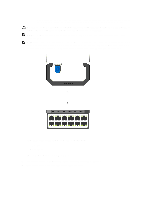
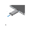
Figure 9. Slide the mounting brackets 1. Utility side of the chassis 2. Mounting Bracket 3. Holding Bracket (factory installed) Rack Mounting Safety Considerations You may either place the switch on the rack shelf or mount the switch directly into a 19" wide, EIA-310-E- compliant rack. • Rack loading - Overloading or uneven loading of racks may result in shelf or rack failure, which may damage equipment and cause possible personal injury. Stabilize racks in a permanent location before loading begins. Mount the components beginning at the bottom of the rack, then work to the top. Do not exceed your rack load rating. • Power considerations - Connect only to the power source specified on the unit. When multiple electrical components are installed in a rack, ensure that the total component power ratings do not exceed the circuit capabilities. Overloaded power sources and extension cords present fire and shock hazards. • Elevated ambient temperature - If installed in a closed rack assembly, the operating temperature of the rack environment may be greater than the room ambient temperature. Use care not to exceed the 40°C maximum ambient temperature of the switch. • Reduced air flow - Install the equipment in the rack so that the amount of airflow required for safe operation of the equipment is not compromised. • Reverse air flow - Necessary clearance is required to ensure cool air intake and to avoid hot air blow out from I/O panel. • Reliable earthing - Maintain reliable earthing of rack-mounted equipment. Pay particular attention to the supply connections other than the direct connections to the branch circuit; for example, use of power strips. • Do not mount the equipment with the Utility panel facing in the downward position. WARNING: These instructions are a condensed reference. Read the safety instructions in your Safety, Environmental, and Regulatory information booklet before you begin. NOTE: The illustrations in this document are not intended to represent a specific switch. 23
-
 1
1 -
2
-
3
-
4
-
5
-
6
-
7
-
8
-
9
-
10
-
11
-
12
-
13
-
14
-
15
-
16
-
17
-
 18
18 -
 19
19 -
 20
20 -
 21
21 -
 22
22 -
 23
23 -
 24
24 -
 25
25 -
 26
26 -
 27
27 -
 28
28 -
29
-
30
-
31
-
32
-
33
-
34
-
35
-
36
-
37
-
38
-
39
-
40
-
41
-
42
-
43
-
44
-
45
-
46
-
47
-
48
-
49
-
50
 |
 |
