Dell Force10 S5000 Installation Guide - Page 31
Assembling and Connecting the Safety Ground Wire for DC Power Supply
 |
View all Dell Force10 S5000 manuals
Add to My Manuals
Save this manual to your list of manuals |
Page 31 highlights
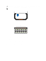
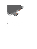
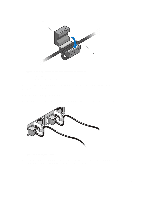
WARNING: Although the switch can run on one PSU, Dell Networking highly recommends using two PSUs for full redundancy and proper cooling. If the switch needs to run with only one PSU for a time, be sure to cover the second PSU slot opening with a blank plate to avoid overheating. WARNING: The Utility panel consists of four slots numbered from 0 to 3. Insert PSUs in slots 0 and 3. WARNING: The PCB edge connector is at the bottom of the switch. Avoid installing the switch upside down. WARNING: Electrostatic discharge (ESD) damage can occur if components are mishandled. Always wear an ESDpreventive wrist or heel ground strap when handling the S5000 and its components. CAUTION: DO NOT mix airflow directions. The airflow directions are color coded. A red label indicates that hot air is expelled from the PSU and a blue label indicates that hot air is expelled from the I/O. Both fans must use the same airflow direction (I/O to Utility or Utility to I/O). The power supplies and fans must have the same color strap. If you mismatch the airflows, the following error message appears and the system shuts down: 00:02:19: %S5000:0 %CHMGR-2-PSU_TYPE_AIRFLOW_MISMATCH: Mismatching PSU airflow detected. Unit 0 shall get shutdown in next 60 seconds if mismatch not rectified. 00:02:19: %STKUNIT0-M:CP %CHMGR-1PSU_AIRFLOW_COMBO_MISMATCH: Major alarm: Mismatching PSU airflow detected in unit 0 Assembling and Connecting the Safety Ground Wire for DC Power Supply WARNING: For equipment using -(48-60) V DC power supplies, a qualified electrician must perform all connections to DC power and to safety grounds. Do not attempt connecting to DC power or installing grounds yourself. All electrical wiring must comply with applicable local or national codes and practices. Damage due to servicing that Dell Networking did not authorize is not covered by your warranty. 1. Strip the insulation from the end of the green/yellow wire, exposing approximately 4.5 mm (0.175 inch) of copper wire. 2. Using a hand-crimping tool (Tyco Electronics, 58433-3 or equivalent), crimp the ring-tongue terminal (Jeeson Terminals Inc., R5-4SA or equivalent) to the green/yellow wire (safety ground wire). 3. Connect the safety ground wire to the grounding post on the back of the system using a #6-32 nut equipped with a locking washer. 31
-
 1
1 -
2
-
3
-
4
-
5
-
6
-
7
-
8
-
9
-
10
-
11
-
12
-
13
-
14
-
15
-
16
-
17
-
18
-
19
-
20
-
21
-
22
-
23
-
24
-
25
-
 26
26 -
 27
27 -
 28
28 -
 29
29 -
 30
30 -
 31
31 -
 32
32 -
 33
33 -
 34
34 -
 35
35 -
 36
36 -
37
-
38
-
39
-
40
-
41
-
42
-
43
-
44
-
45
-
46
-
47
-
48
-
49
-
50
 |
 |