Dell Force10 S5000 Installation Guide - Page 33
Slot 0 for DC PSU 0, Installing a DC Power Supply
 |
View all Dell Force10 S5000 manuals
Add to My Manuals
Save this manual to your list of manuals |
Page 33 highlights
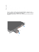
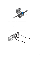
Figure 18. Installing a DC Power Supply 1. Slot 0 (for DC PSU 0) 2. Release latch 3. Strip the insulation from the ends of the DC power wires, exposing approximately 13 mm (0.5 inch) of copper wire. WARNING: Reversing polarity when connecting DC power wires can permanently damage the power supply or the system. 4. Insert the copper ends into the mating connectors and tighten the captive screws at the top of the mating connector using a #2 Phillips screwdriver. WARNING: To protect the power supply from electrostatic discharge, you must cover the captive screws with the rubber cap before inserting the mating connector into the power supply. 5. Rotate the rubber cap clockwise to fix it over the captive screws. 6. Insert the mating connector into the power supply. 33
-
 1
1 -
2
-
3
-
4
-
5
-
6
-
7
-
8
-
9
-
10
-
11
-
12
-
13
-
14
-
15
-
16
-
17
-
18
-
19
-
20
-
21
-
22
-
23
-
24
-
25
-
26
-
27
-
 28
28 -
 29
29 -
 30
30 -
 31
31 -
 32
32 -
 33
33 -
 34
34 -
 35
35 -
 36
36 -
 37
37 -
 38
38 -
39
-
40
-
41
-
42
-
43
-
44
-
45
-
46
-
47
-
48
-
49
-
50
 |
 |
