Dell Force10 S5000 Installation Guide - Page 26
Replacing an Ethernet Module, Important Points to Remember for Installing a Fibre Channel Module
 |
View all Dell Force10 S5000 manuals
Add to My Manuals
Save this manual to your list of manuals |
Page 26 highlights
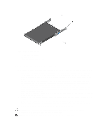
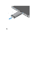
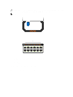
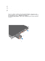
Figure 12. Installing an Ethernet Module 1. Release latch 2. Ethernet Module Replacing an Ethernet Module NOTE: S5000 does not support the hot swapping of an Ethernet pluggable module during switch operations. Instead, you must power down the switch before removing and replacing an expansion module. 1. Disconnect any network interface cables attached to the module. 2. Use the grab handle to slide the Ethernet module out of the switch module slot. 3. Use the grab handle on the replacement Ethernet module to slide it into the switch module slot. 4. Connect any network interface cables to the attached module. Important Points to Remember for Installing a Fibre Channel Module • You must insert the Fibre Channel module only in slot 0. • Installing and swapping of Fibre Channel modules must be done BEFORE power up. If you need to install or replace a module, power down the system before you install or replace it. If you install or replace a module when the system is powered up, the system does not recognize the module. Online insertion of modules can result in a catastrophic failure. • The S5000 does not support the hot swapping of a Fibre Channel pluggable module during switch operations. Instead, you must power down the switch before removing and replacing a Fibre Channel module. • Although the handle and port numbering may appear differently on a Fibre Channel module, there is no functional difference. A module may have: - A larger handle that covers the entire front of the module and has the part number written on top of the handle. Port numbering is written on the front of the handle. - A smaller handle that is half the size and does not cover the release button. The part number is written on the front of the handle. Port numbering is written on the lower part of the front of the module. 26
-
 1
1 -
2
-
3
-
4
-
5
-
6
-
7
-
8
-
9
-
10
-
11
-
12
-
13
-
14
-
15
-
16
-
17
-
18
-
19
-
20
-
 21
21 -
 22
22 -
 23
23 -
 24
24 -
 25
25 -
 26
26 -
 27
27 -
 28
28 -
 29
29 -
 30
30 -
 31
31 -
32
-
33
-
34
-
35
-
36
-
37
-
38
-
39
-
40
-
41
-
42
-
43
-
44
-
45
-
46
-
47
-
48
-
49
-
50
 |
 |
