Dell Force10 S6000 Installation Guide - Page 24
Configuring a Two-Post Flush-Mount, Two-Post Flush-Mount Configuration
 |
View all Dell Force10 S6000 manuals
Add to My Manuals
Save this manual to your list of manuals |
Page 24 highlights
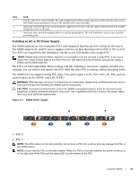
www.dell.com | support.dell.com Configuring a Two-Post Flush-Mount Step Task 1 For this configuration, remove the castings from the front side of each ReadyRails assembly. Refer to Figure 4-2, item 1. To remove the two screws from each front flange ear (on the switch side of the rail) and remove each casting, use a Torx driver. Retain the castings for future rack requirements. It is not necessary to remove the rear flange castings. Figure 4-2. Two-Post Flush-Mount Configuration 2 Attach one rail to the front post flange with two user-supplied screws. Refer to Figure 4-2, item 2. 3 Slide the plunger bracket forward against the vertical post and secure the plunger bracket to the post flange with two user-supplied screws. Refer to Figure 4-2, item 3. 4 Repeat this procedure for the second rail. 24 | Install the S6000
-
 1
1 -
2
-
3
-
4
-
5
-
6
-
7
-
8
-
9
-
10
-
11
-
12
-
13
-
14
-
15
-
16
-
17
-
18
-
 19
19 -
 20
20 -
 21
21 -
 22
22 -
 23
23 -
 24
24 -
 25
25 -
 26
26 -
 27
27 -
 28
28 -
 29
29 -
30
-
31
-
32
-
33
-
34
-
35
-
36
-
37
-
38
-
39
-
40
-
41
-
42
-
43
-
44
-
45
-
46
-
47
-
48
-
49
-
50
-
51
-
52
-
53
-
54
-
55
-
56
 |
 |
