Dell Inspiron 16 5635 Owners Manual - Page 68
Installing the system board, Steps, Prerequisites
 |
View all Dell Inspiron 16 5635 manuals
Add to My Manuals
Save this manual to your list of manuals |
Page 68 highlights
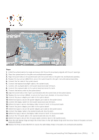
Steps 1. Remove the three screws (M2.5x5) that secure the right display hinge to the system board. 2. Open the right display hinge at an angle of 90 degrees. 3. Remove the two screws (M2x4) that secure the USB-C bracket to the system board. 4. Lift the USB-C bracket off the system board. 5. Peel the tape that secures the display-cable connector latch to the system board. 6. Open the latch and disconnect the display cable from the system board. 7. Peel the tapes that secure the power-adapter port cable to the system board. 8. Disconnect the power-adapter port cable from the system board. 9. Peel the tapes that secure the I/O board cable to the system board. 10. Open the latch and disconnect the I/O board cable to the system board. 11. Disconnect the battery cable from the system board. 12. Open the latch and disconnect the keyboard cable from the system board. 13. Open the latch and disconnect the touchpad cable from the system board. 14. Disconnect the keyboard-backlight cable from the system board. 15. Disconnect the fan cable from the system board. 16. Remove the two screws (M2x1.8) that secure the system board to the palm-rest and keyboard assembly. 17. Lift the system board at angle off the palm-rest and keyboard assembly, to clear the ports from the port openings. Installing the system board Prerequisites CAUTION: The information in this section is intended for authorized service technicians only. If you are replacing a component, remove the existing component before performing the installation process. 68 Removing and installing Field Replaceable Units (FRUs)
-
 1
1 -
2
-
3
-
4
-
5
-
6
-
7
-
8
-
9
-
10
-
11
-
12
-
13
-
14
-
15
-
16
-
17
-
18
-
19
-
20
-
21
-
22
-
23
-
24
-
25
-
26
-
27
-
28
-
29
-
30
-
31
-
32
-
33
-
34
-
35
-
36
-
37
-
38
-
39
-
40
-
41
-
42
-
43
-
44
-
45
-
46
-
47
-
48
-
49
-
50
-
51
-
52
-
53
-
54
-
55
-
56
-
57
-
58
-
59
-
60
-
61
-
62
-
 63
63 -
 64
64 -
 65
65 -
 66
66 -
 67
67 -
 68
68 -
 69
69 -
 70
70 -
 71
71 -
 72
72 -
 73
73 -
74
-
75
-
76
-
77
-
78
-
79
-
80
-
81
-
82
-
83
-
84
-
85
-
86
-
87
-
88
-
89
-
90
-
91
-
92
 |
 |
